Planar light-emitting apparatus

a light-emitting apparatus and planar technology, applied in lighting and heating apparatus, lighting device details, instruments, etc., can solve the problems of unsatisfactory demand and and achieve the effect of reducing uneven brightness of gradation on display surfaces

Inactive Publication Date: 2010-06-24
SONY CORP
View PDF5 Cites 19 Cited by
  • Summary
  • Abstract
  • Description
  • Claims
  • Application Information

AI Technical Summary

Benefits of technology

[0006]In view of the above-described situation, it is desirable to reduce the brightness unevenness in gradation on a display surface.
[0016]Thus, according to the embodiments of the present invention, the brightness unevenness in gradation on the display surface can be reduced.

Problems solved by technology

However, in the case where a backlight according to the related art is used, there is a possibility that brightness unevenness in gradation will occur on a display surface of the liquid crystal display apparatus.
However, the demand has not been fully satisfied.

Method used


Image

  • Planar light-emitting apparatus
  • Planar light-emitting apparatus
  • Planar light-emitting apparatus

Examples


first embodiment

1. Planar Light-Emitting Apparatus of the Present Invention

[0033]Exemplary Structure of Backlight which Functions as Planar Light-Emitting Apparatus According to First Embodiment

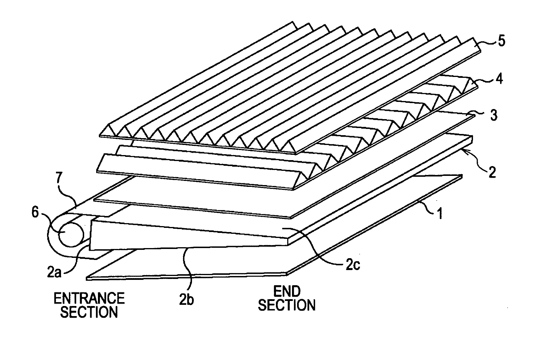
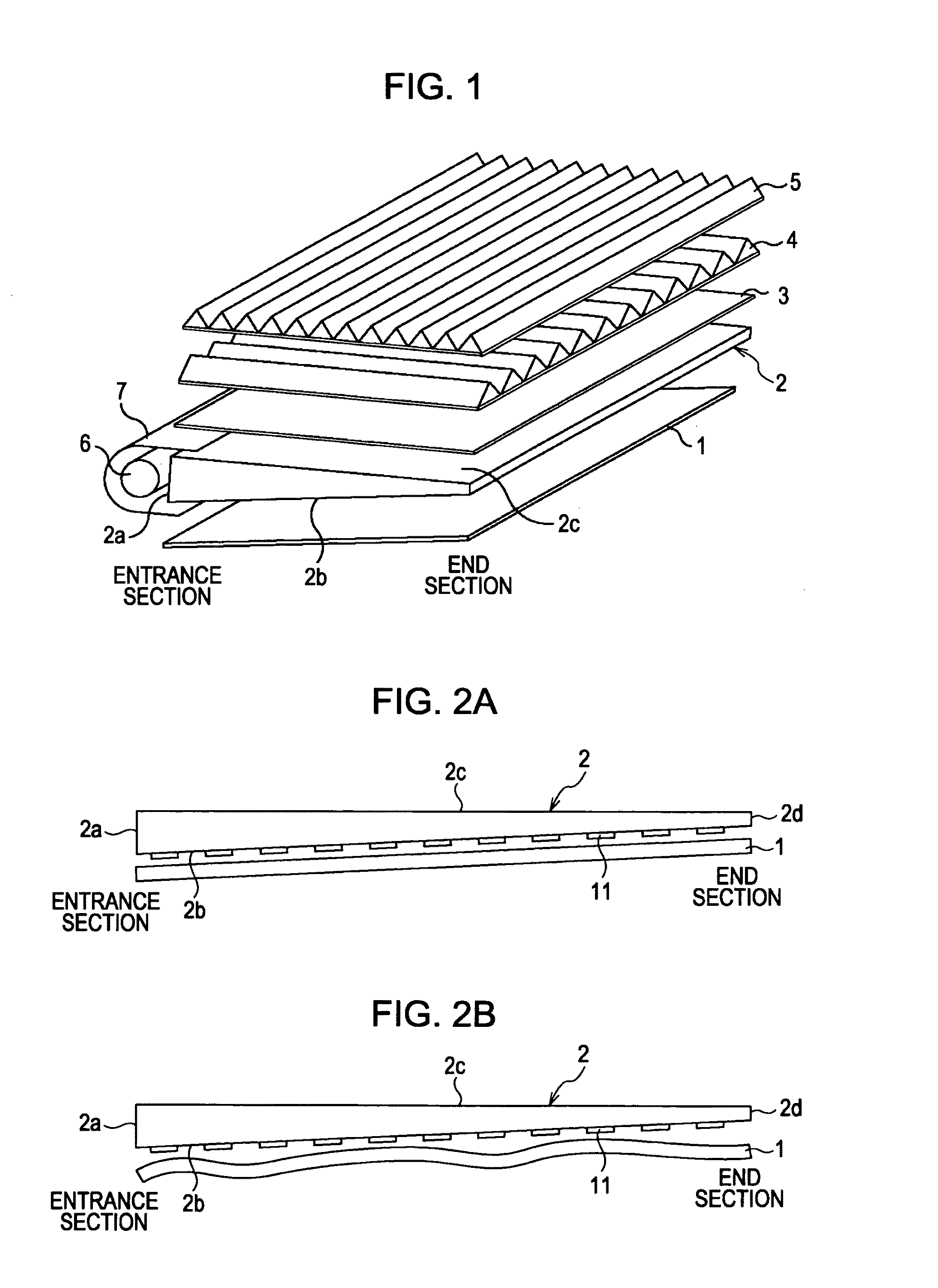
[0034]FIG. 1 is a diagram illustrating an exemplary structure of a backlight which functions as a planar light-emitting apparatus according to an embodiment of the present invention. The backlight is included in a liquid crystal display apparatus included in, for example, a notebook personal computer.

[0035]The backlight shown in FIG. 1 includes a reflecting plate 1, an optical waveguide 2, a diffusing sheet 3, a vertical prism sheet 4, a horizontal prism sheet 5, a cold-cathode tube 6, and a reflector 7.

[0036]The optical waveguide 2 has a so-called wedge shape. The cold-cathode tube 6 is disposed near a side surface 2a (left side surface 2a in FIG. 1) of the optical waveguide 2. The cold-cathode tube 6 functions as a light source and is provided with the reflector 7. Thus, the optical waveguide 2 is structu...

second embodiment

2. Planar Light-Emitting Apparatus of Present Invention

[0089]Exemplary Structure of Backlight which Functions as Planar Light-Emitting Apparatus According to Second Embodiment

[0090]FIG. 14 is a diagram illustrating an exemplary structure of a backlight which functions as a planar light-emitting apparatus according to an embodiment of the present invention. The backlight is included in a liquid crystal display apparatus included in, for example, a notebook personal computer. This example is different from the example shown in FIG. 1.

[0091]The backlight shown in FIG. 14 includes a reflecting sheet 31, an optical waveguide 2, a diffusing film 32, a prism sheet 33, and LEDs 34.

[0092]The LEDs 34 are disposed near a side surface 2a (left side surface 2a in FIG. 14) of the optical waveguide 2. Thus, the optical waveguide 2 is structured such that light emitted from the light source is incident on the side surface 2a and is guided to the inner section of the optical waveguide 2.

[0093]The r...


PUM


Abstract

A planar light-emitting apparatus includes a light source, a light-guiding member configured to allow light from the light source to propagate therethrough, a reflecting member disposed such that the reflecting member faces the light-guiding member, the reflecting member reflecting the light propagating through the light-guiding member, and an adhesive member configured to attach the light-guiding member and the reflecting member to each other. A distribution of an adhesive region of the adhesive member on a surface of the light-guiding member is determined on the basis of a brightness distribution of the planar light-emitting apparatus in the case where the adhesive member is uniformly distributed on the surface of the light-guiding member, and the adhesive member is formed between the light-guiding member and the reflecting member in accordance with the distribution of the adhesive region.

Description

BACKGROUND OF THE INVENTION[0001]1. Field of the Invention[0002]The present invention relates to planar light-emitting apparatuses, and more particularly, to a planar light-emitting apparatus in which brightness unevenness in gradation on a display surface is reduced.[0003]2. Description of the Related Art[0004]Recently, liquid-crystal display apparatuses have come into widespread use. The liquid crystal display apparatuses display images by controlling the transmittance of light incident on a liquid crystal panel at each pixel. Therefore, the liquid crystal panel is generally provided with a backlight which causes light to be incident on the liquid crystal panel (see, for example, Japanese Unexamined Patent Application Publication No. 11-174976).SUMMARY OF THE INVENTION[0005]However, in the case where a backlight according to the related art is used, there is a possibility that brightness unevenness in gradation will occur on a display surface of the liquid crystal display apparatu...

Claims


Application Information

Patent Timeline
Patent Type & Authority Applications(United States)
IPC IPC(8): F21V7/04
CPCG02B6/0043G02B6/0055G02F2202/28G02F1/133553G02F1/133615G02B6/0061
Inventor TANAHASHI, MAKOTO
Owner SONY CORP
Why Eureka
Try Eureka