Resilient attachment to provider link state bridging (PLSB) networks

a technology of provider link state and resilient attachment, which is applied in the direction of data switching network, sustainable buildings, high-level techniques, etc., can solve the problems of one of the paths that must be logically disabled, and no simple way of extending the link aggregation group across the ethernet domain between the peer smlt-enabled ess

Inactive Publication Date: 2010-06-24
RPX CLEARINGHOUSE
View PDF7 Cites 85 Cited by
  • Summary
  • Abstract
  • Description
  • Claims
  • Application Information

AI Technical Summary

Problems solved by technology

However, there is no simple way of extending the link aggregation group across the Ethernet domain between the peer SMLT-enabled ESs and, for example, a second set of peer SMLT-enabled ESs supporting a second CS.
However, in order to prevent looping, and consequent failure of the network, one of these paths must be logically disabled.

Method used


Image

  • Resilient attachment to provider link state bridging (PLSB) networks
  • Resilient attachment to provider link state bridging (PLSB) networks
  • Resilient attachment to provider link state bridging (PLSB) networks

Examples


Embodiment Construction

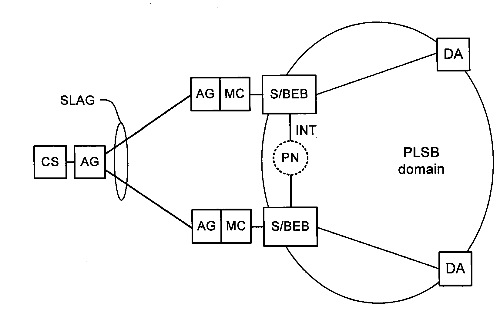
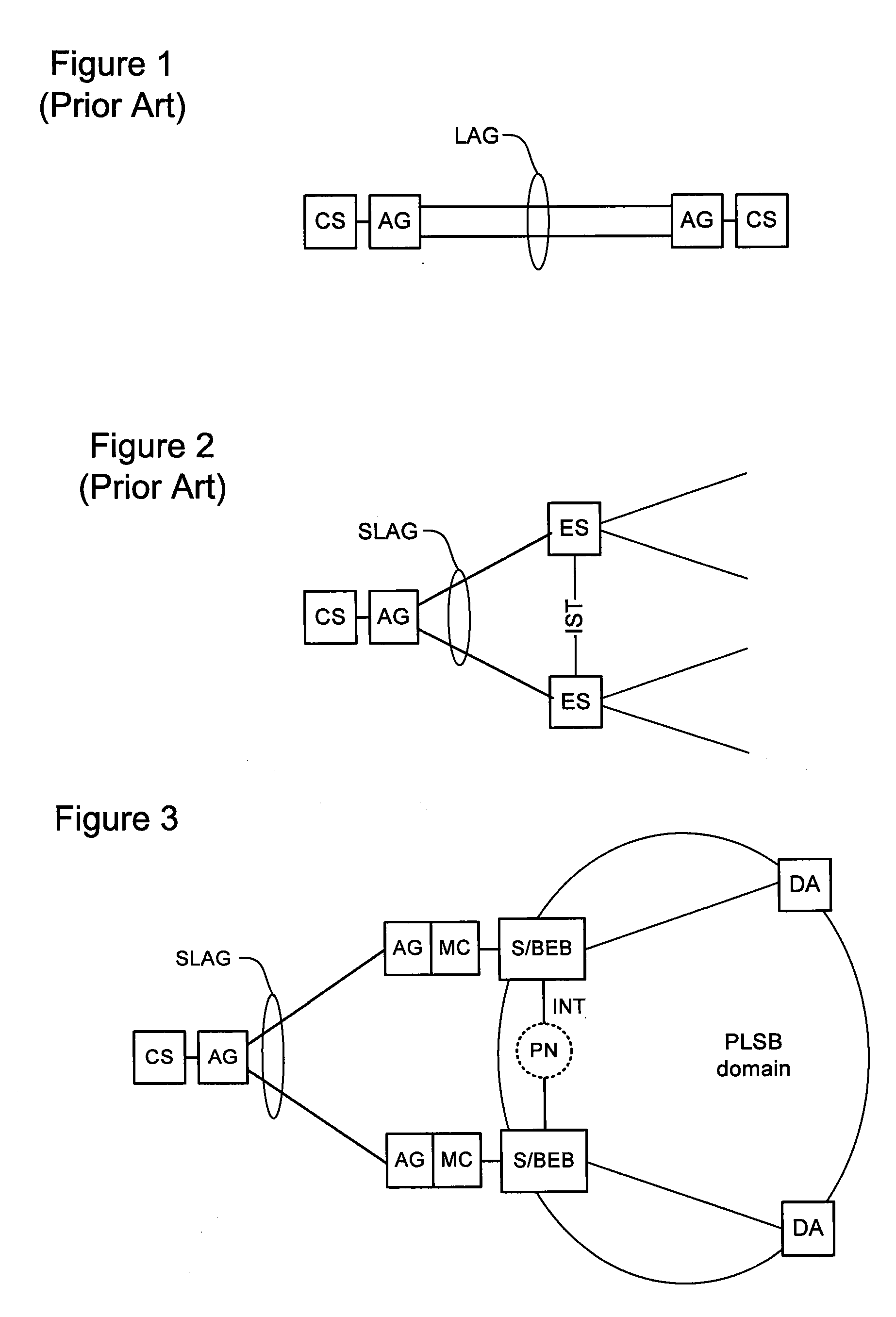
[0019]The present invention provides a method of utilizing link aggregation as a form of resilient access to a PLSB network. Embodiments of the invention are described below, by way of example only, with reference to FIGS. 3-5.

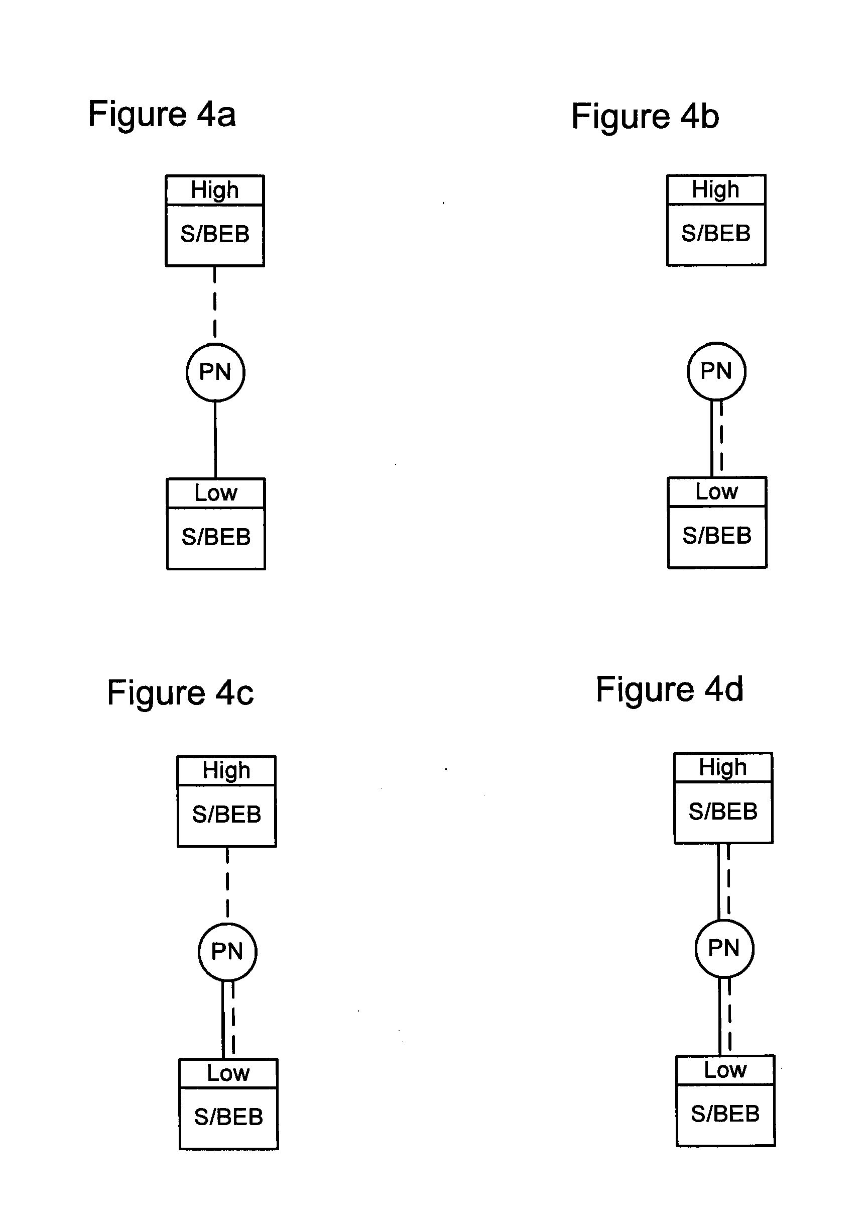
[0020]In very general terms, the present invention enables resilient connection to a network domain whereby the assignment of traffic by a client system (CS) to the plurality of links of a Split Link Aggregation Group (SLAG), in the upstream direction, is arbitrary, and extension of such resiliency across a network domain by extending parallel connections though the domain to the desired egress points from the network domain. These egress points may be other Ethernet Switches (ESs) or a virtualized CS in a singular ES that proxies the function on behalf of the single attached client. In preferred embodiments, this is accomplished by providing a set of two or more peer edge nodes of the network domain, each one of the set of peer edge nodes including at least o...


PUM


Abstract

A method system for interfacing a client system in a first network domain with a Provider Link State Bridging (PLSB) network domain. At least two Backbone Edge Bridges (BEBs) of the PLSB domain 20 are provided. Each BEB is an end-point of a connection in the first network domain to the client system and an end-point of at least a unicast path defined within the PLSB domain 20. An inter-node trunk is provided in the PLSB domain 20 for interconnecting the at least two BEBs. A phantom node is defined in the PLSB domain 20. The phantom node has a unique address in the PLSB domain 20 and is notionally located on the inter-node trunk one hop from each of the BEBs. Each of the BEBs is configured such that: an ingress packet received from the client system via the connection in the first network domain is forwarded through a path notionally rooted at the phantom node; and an egress subscriber packet destined for the client system is forwarded to the client system through the connection in the first network domain.

Description

CROSS-REFERENCE TO RELATED APPLICATIONS[0001]This is the first application filed for the present invention.MICROFICHE APPENDIX[0002]Not Applicable.TECHNICAL FIELD[0003]The present invention relates to management of traffic forwarding in packet networks, and in particular to methods of resiliently attaching Ethernet to Provider Link State Bridging (PLSB) networks.BACKGROUND OF THE INVENTION[0004]Network operators and carriers are deploying packet-switched communications networks in place of circuit-switched networks. In packet-switched networks such as Internet Protocol (IP) networks, IP packets are routed according to routing state stored at each IP router in the network. Similarly, in Ethernet networks, Ethernet frames are forwarded according to forwarding state stored at each Ethernet switch in the network. The present invention applies to communications networks employing any Protocol Data Unit (PDU) based network and in this document, the terms “packet” and “packet-switched netw...

Claims


Application Information

Patent Timeline
Patent Type & Authority Applications(United States)
IPC IPC(8): H04L12/28H04L45/24H04L45/243H04L45/02H04L45/74H04L47/41
CPCH04L45/02H04L45/245H04L45/48H04L2212/0025H04L45/74H04L45/22H04L12/66H04L47/41H04L41/0654Y02B60/33H04L2212/00Y02D30/50H04L45/03H04L45/06H04L12/46
Inventor CASEY, LIAMALLAN, DAVIDBRAGG, NIGEL L.CHIABAUT, JEROMEASHWOOD SMITH, PETER
Owner RPX CLEARINGHOUSE
Why Eureka
Try Eureka