
Tack set for use on bulletin boards

a bulletin board and set technology, applied in the field of set, can solve the problems of inconvenient removal of the push pin, difficulty in finding the push pin if lost, and the safety of users

Inactive Publication Date: 2010-06-24
PARK SUNG JIN
View PDF0 Cites 1 Cited by
  • Summary
  • Abstract
  • Description
  • Claims
  • Application Information

AI Technical Summary

Benefits of technology

[0006]An object of the present invention is to provide a tack set capable of being used to more firmly fix an item to be posted and easily remove it.
[0008]A further object of the present invention is to provide a tack set for fixation of an item to be posted, having an improved shape and structure thereof, capable of facilitating fixation and removal of the item to be posted through a rectangular-shaped thin plate and fixing pins formed at predetermined positions on the thin plate.

Problems solved by technology

However, a fingernail, or a separate tool must be used to remove this conventional push-pin, thereby causing inconvenience in the removal of the push-pin.
Further, since the push-pin is generally very small in size, it is difficult to locate the push-pin if lost.
Thus, if the straight insertion pin is inverted so that the pointed end is directed upwards, this hurts a user's body if the user steps on the inverted push-pin, thereby generating a problem in terms of a user's safety.

Method used


Image

  • Tack set for use on bulletin boards
  • Tack set for use on bulletin boards
  • Tack set for use on bulletin boards

Examples


first embodiment

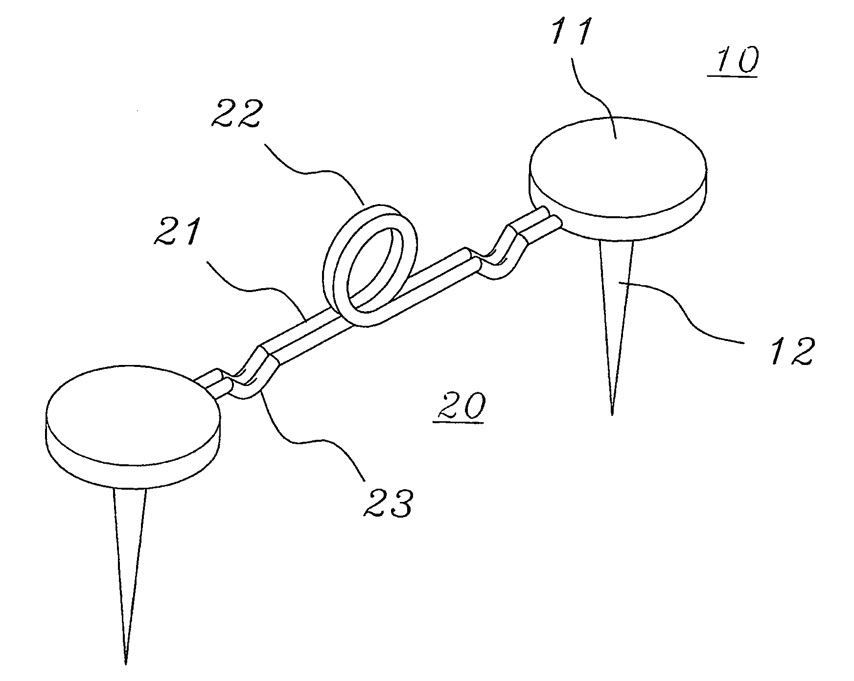
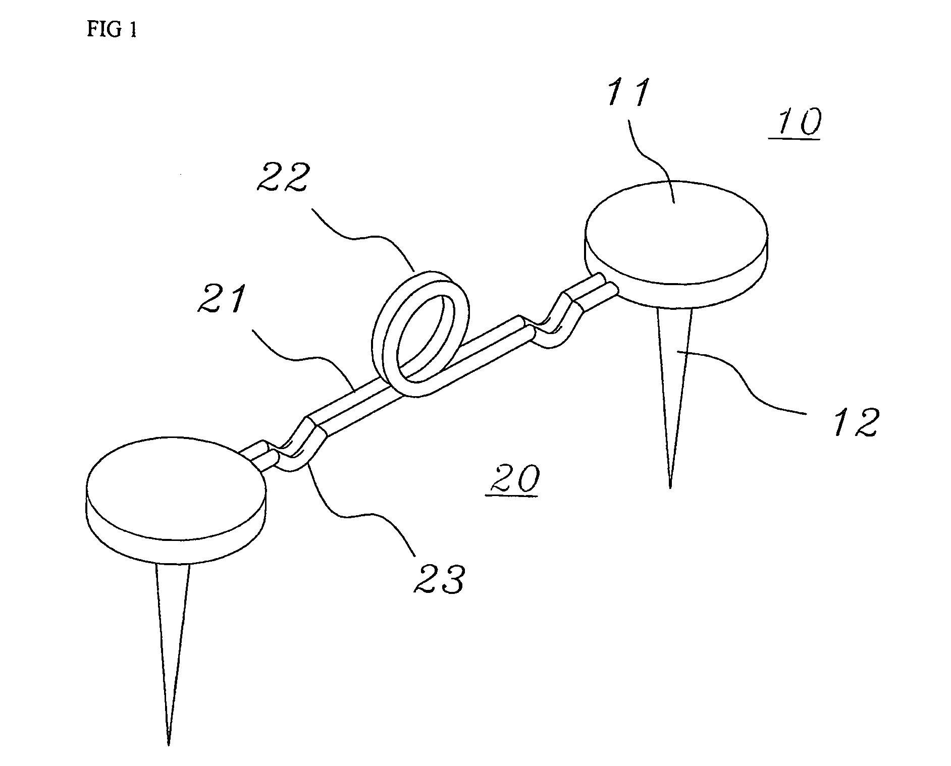
[0010]FIG. 1 is a perspective view of a tack set for fixation of an item to be posted according to the present invention;

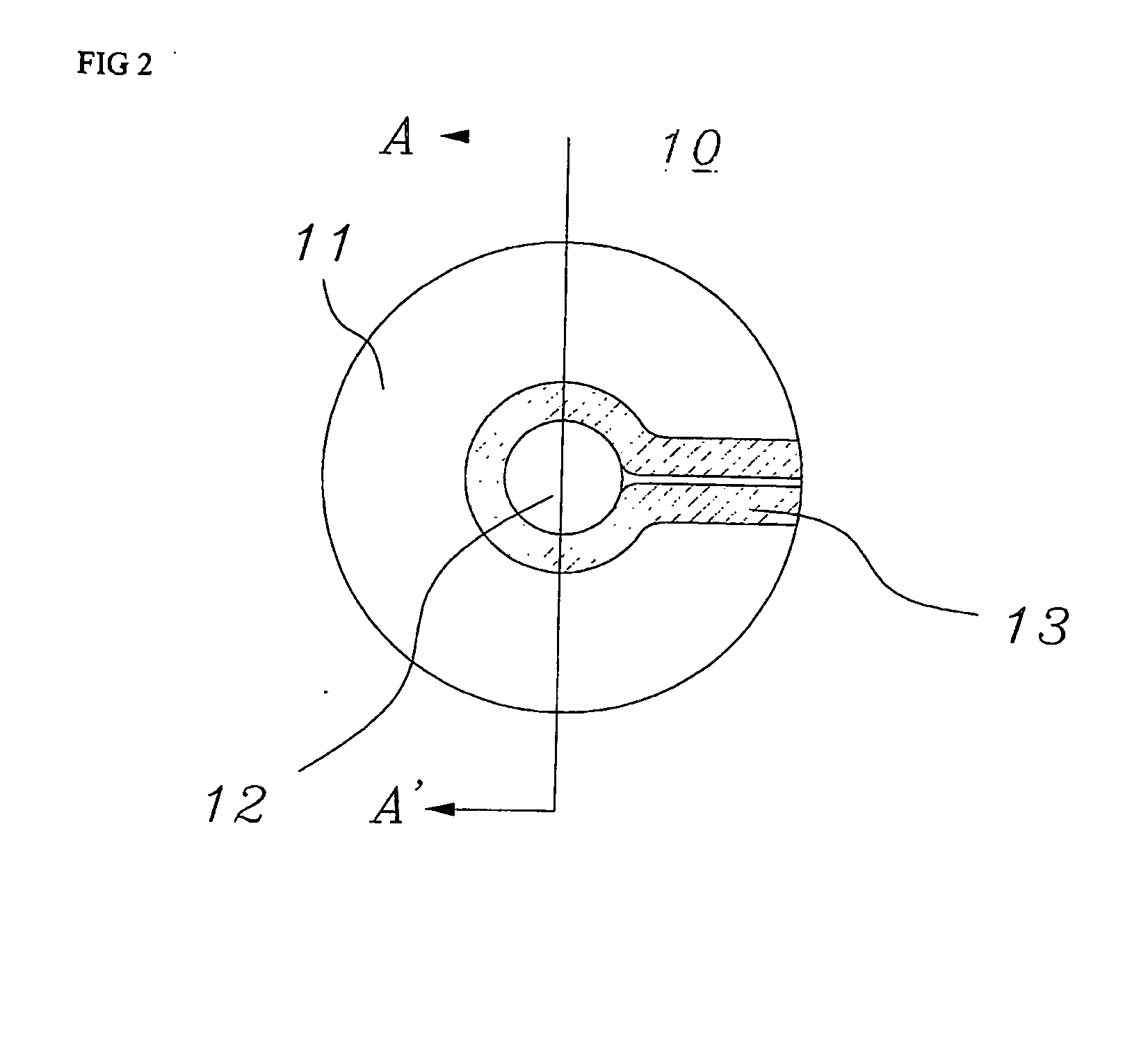
[0011]FIGS. 2 and 3 are respectively a rear view of a tack coupling part having a concave lower surface in the tack set according to the first embodiment of the present invention, and a side sectional view taken along line A-A′ of FIG. 2;

[0012]FIG. 4 is a front view of the tack set for fixation of an item to be posted according to the first embodiment of the present invention;

[0013]FIG. 5 is a perspective view illustrating use of the tack set for fixation of the item to be posted, by inserting a finger into a finger handle according to the first embodiment of the present invention;

[0014]FIGS. 6 and 7 are a front view and a side view illustrating fixation of an item to be posted by use of the tack set for fixation of the item to be posted according to the first embodiment of the present invention;

[0015]FIG. 8 is a perspective view of a connection member having ring...

second embodiment

[0016]FIG. 9 is a perspective view of a tack set for fixation of an item to be posted according to the present invention;

[0017]FIG. 10 is a front view of the tack set for fixation of the item to be posted according to the second embodiment of the present invention;

[0018]FIG. 11 is a perspective view illustrating use by a user of the tack set for fixation of the item to be posted according to the second embodiment of the present invention; and

[0019]FIG. 12 is a front view illustrating fixation by the tack set of the item to be posted on a bulletin board according to the second embodiment of the present invention.


PUM


Abstract

A tack set to fix items to be posted is disclosed. The tack set is configured as a first embodiment wherein a fixing pin having a coupling part and a wire formed with a loop and coupled with the coupling part in order to be connected to the fixing pin are formed, or a connection member is not integral with the fixing pin but is formed with push-pin rings on both ends thereof, through which the pin of a conventional push-pin may be inserted and removed, thereby being capable of attaching or detaching items to be posted with a fixing pin or a conventional insertion pin, and a second embodiment having an improved shape and structure of the tack set, capable of facilitating fixation or removal of items to be posted with the fixing pin through a rectangular-shaped thin plate having coupling parts shaped with continuous convex and concave portions and fixing pins formed on predetermined opposite positions of the thin plate, to fix the items to be posted.

Description

TECHNICAL FIELD[0001]The present invention relates, in general, to a tack set used to fix notices or memos to be posted (“item to be posted”) on a bulletin board and, more particularly, to a tack set to fix items to be posted, configured as a first embodiment wherein a fixing pin having a coupling part and a wire formed with a loop and coupled with the coupling part in order to be connected to the fixing pin are formed, or a connection member is not integral with the fixing pin but is formed with push-pin rings on both ends thereof, through which the pin of a conventional push-pin may be inserted and removed, thereby being capable of attaching or detaching items to be posted with a fixing pin or a conventional insertion pin, and a second embodiment having an improved shape and structure of the tack set, capable of facilitating fixation or removal of items to be posted with the fixing pin through a rectangular-shaped thin plate having coupling parts shaped with continuous convex and ...

Claims


Application Information

Patent Timeline
IPC IPC(8): B43M15/00F16B15/00
CPCB43M15/00
Inventor PARK, SUNG JIN
Owner PARK SUNG JIN
Learn More