Low Profile Dual Locking Fixation System and Offset Anchor Member

a fixation system and low-profile technology, applied in the field of low-profile screw assembly, can solve the problems of increasing the chance of tissue damage in and around the surgical site during installation, increasing the difficulty of assembling and/or installing many devices, and increasing the height of the assembly. , to achieve the effect of minimizing the height of the assembly

Inactive Publication Date: 2010-06-24
PIONEER SURGICAL TECH INC
View PDF99 Cites 170 Cited by
  • Summary
  • Abstract
  • Description
  • Claims
  • Application Information

AI Technical Summary

Benefits of technology

[0007]An exemplary coupling device configured to couple a spinal rod to the head of a bone anchor includes a generally cylindrical insert axially received in an interior space of an annular outer member to form a tulip-shaped assembly. The insert member may include a lower portion with a generally spherical cavity configured to receive the head of an anchor member and an upper portion having a rod-receiving channel or seat. According to one exemplary embodiment, flexible, upstanding, laterally-spaced arms are arranged on either side of the channel and are configured to provisionally couple an elongate member by resiliently deflecting to grip a rod placed in the channel. The exemplary coupling assembly also includes an outer member or body having a bore, with at least a portion of the bore sized and configured to compress the insert member. After the head of the anchor member is received in the lower portion of the insert member, the outer member may be moved over the outer surface of the insert member, compressing the insert member to compressibly lock its lower portion onto the bone fixation device. Moreover, a rod retaining device engages the insert member and applies a compressive force radially toward the rod to secure the position of the rod. For instance, the rod retaining device may be provided in the form of a cap with at least one depending leg configured for friction fitting between the insert member and the outer member. Preferably, projections from the ...

Problems solved by technology

For instance, some pedicle screw systems include rather large and bulky assemblies to secure a rod, thus increasing opportunities for tissue damage in and around the surgical site during installation.
Many dev...

Method used


Image

  • Low Profile Dual Locking Fixation System and Offset Anchor Member
  • Low Profile Dual Locking Fixation System and Offset Anchor Member
  • Low Profile Dual Locking Fixation System and Offset Anchor Member

Examples


Embodiment Construction

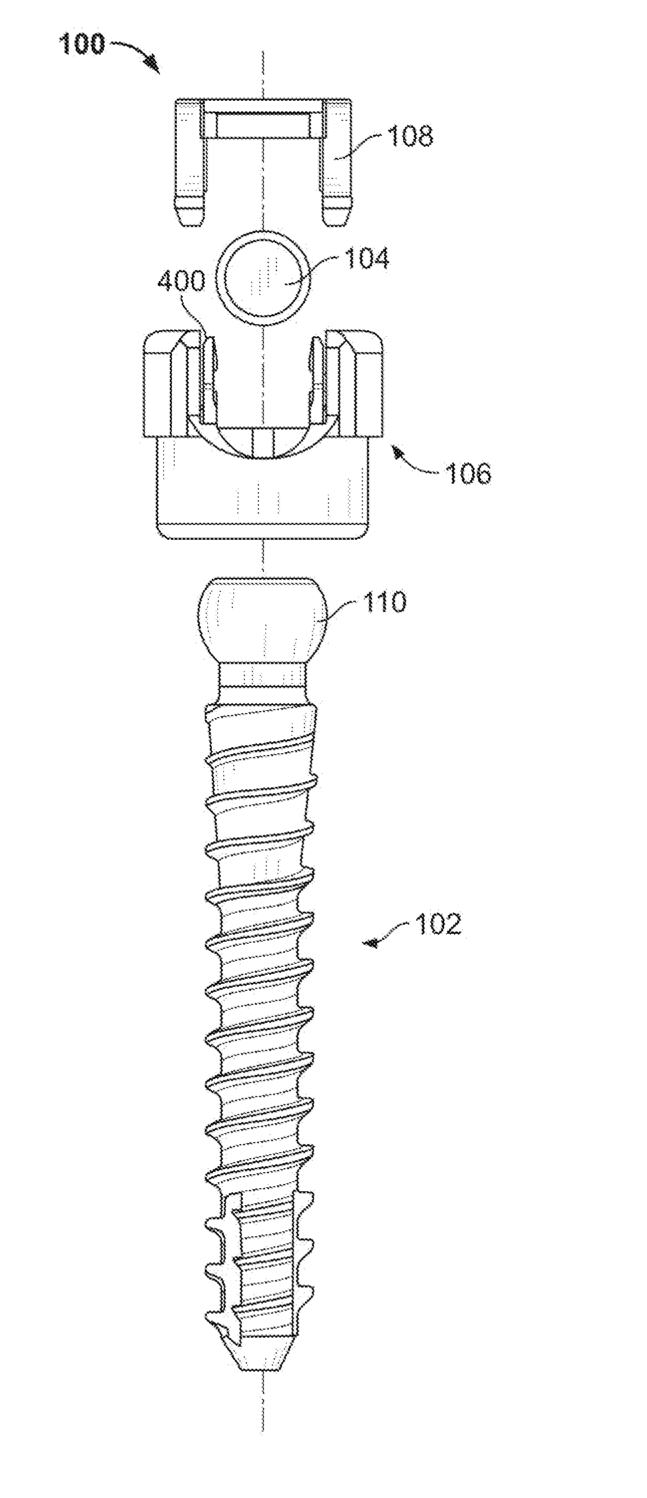
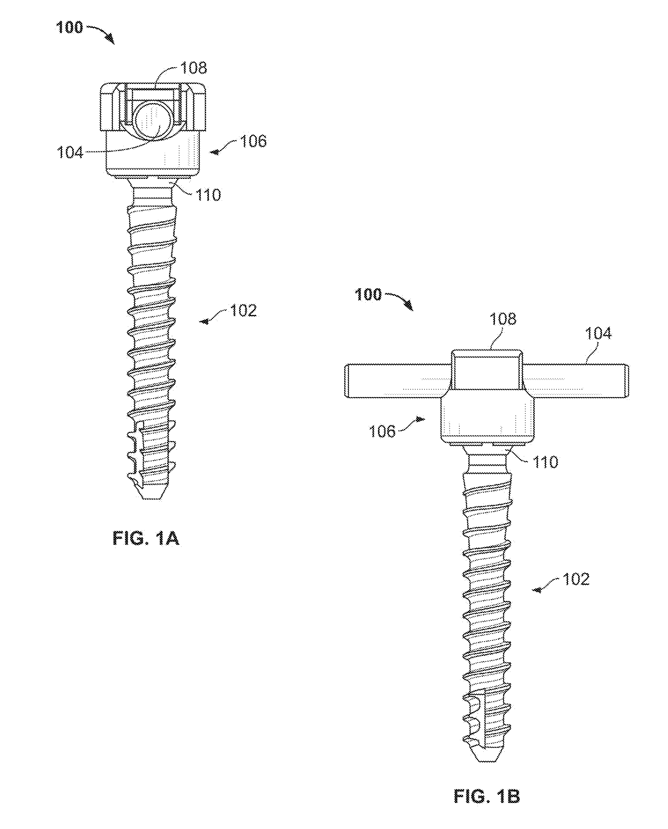
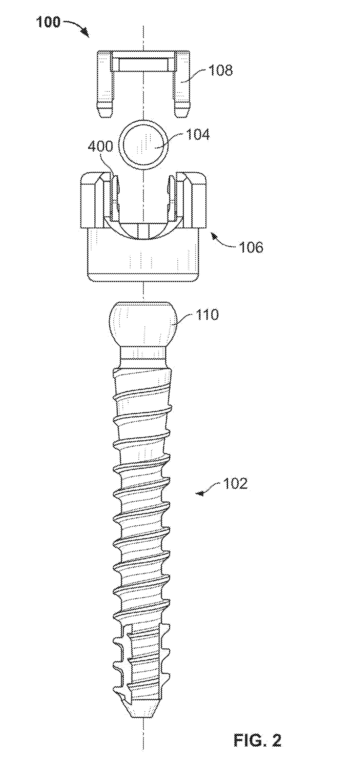
[0066]FIGS. 1-43 illustrate systems and methods for locking the orientation of an anchor member and elongate member with respect to a first type of coupling assembly, sometimes referred to as a “tulip assembly,” in which an insert member is inserted linearly into a space within an outer member. Axial shifting of the outer member and insert relative to one another (and the consequent radial compression exerted thereby) locks the position of the coupling assembly relative to an anchor member or fixation device (e.g. a pedicle screw or hook). Further, according to one exemplary embodiment, a coupling assembly may be configured to be placed on the head of a polyaxial pedicle screw after placement of the pedicle screw in a patient's body and configured to receive and positionally secure a top loaded rod. Further details of the present exemplary system and method will be provided below.

[0067]By way of example, pedicle screw systems may be fixed in the spine in a posterior lumbar fusion pr...


PUM


Abstract

A coupling device for securing an elongate member to the spine is provided. The coupling device comprises a compressible inner member that secures an anchor member therein when the inner member is axially shifted within an outer member. The elongate member is retained within the device by an axially inserted locking member, and may be secured independently of the anchor member. The coupling device and anchor may be configured to provide increased angulation of the anchor with respect to the coupling device. For instance, anchor member may have an offset head portion in order to provide normal pivoting of the coupling device when the anchor is attached to bone at an angle.

Description

RELATED APPLICATIONS[0001]This application is a non-provisional application claiming the benefit of U.S. Provisional Applications 61 / 105,047 filed Oct. 14, 2008 and 61 / 105,048 filed Oct. 14, 2008, both of which are hereby incorporated by reference as if fully set forth herein.FIELD OF THE INVENTION[0002]The present systems and methods relate to bone fixation devices. More particularly, the present systems and methods provide for a low profile screw assembly configured to facilitate the internal fixation of vertebral bodies.BACKGROUND OF THE INVENTION[0003]Various devices for internal fixation of bone segments in the human or animal body are known in the art. For instance, pedicle screw and / or hook systems are sometimes used as an adjunct to spinal fusion surgery. Such systems may have a rod-receiving portion and an integral anchor portion, or may be provided with a separate anchor member, especially one that may be pivoted with respect to a rod-receiving member. Although pedicle scr...

Claims


Application Information

Patent Timeline
IPC IPC(8): A61B17/86
CPCA61B17/7035A61B17/7052A61B17/8605A61B17/7086A61B17/7082
Inventor GEPHART, MATTHEW P.KNAPP, TROY D.BERMAN, PHILLIP J.
Owner PIONEER SURGICAL TECH INC
Why Eureka
Try Eureka