Float Device

a float device and float technology, applied in vehicle components, filtration separation, functional valve types, etc., can solve the problems of preventing the device from fitting properly, the length of the filter needs to be accurate, and the fuel capacity of the tank is not maximised

Active Publication Date: 2010-07-01
FUEL ACTIVE LTD
View PDF11 Cites 3 Cited by
  • Summary
  • Abstract
  • Description
  • Claims
  • Application Information

AI Technical Summary

Benefits of technology

[0010]In use, the device operates in the same manner as the float device of UK Patent Number GB2 350 337B. However, the lower end of the filter or other member is open thereby allowing the float to extend partially below the filter or other member when the level of fuel in the tank is low. In this way a device with a slightly shorter filter or other member can be fitted into a tank to ensure that the device fits and to allow for manufacturing tolerances or deformations in the tank. However, when the level of fuel is low, the float extends below the level of the filter or other member so that more fuel can be drawn from the tank compared with the device disclosed in UK Patent Number GB2 350 337B. It will be appreciated that a device having a filter or other member of a particular length can thus be fitted to tanks having a range of different depths.

Problems solved by technology

However, a disadvantage of this arrangement is that any water and / or sediment which has accumulated at the bottom of the tank can be drawn up with the fuel.
A disadvantage of this arrangement is that the length of the filter needs to be accurate, otherwise it will abut the bottom of the tank and prevent the device from fitting properly.
Alternatively, if the filter is too short, the pick-up end of the tube will not reach to the bottom of the tank and as such the fuel capacity of the tank is not maximised.

Method used


Image

  • Float Device
  • Float Device

Examples


Embodiment Construction

[0020]An embodiment of the present invention will now be described by way of an example only and with reference to the accompanying drawing.

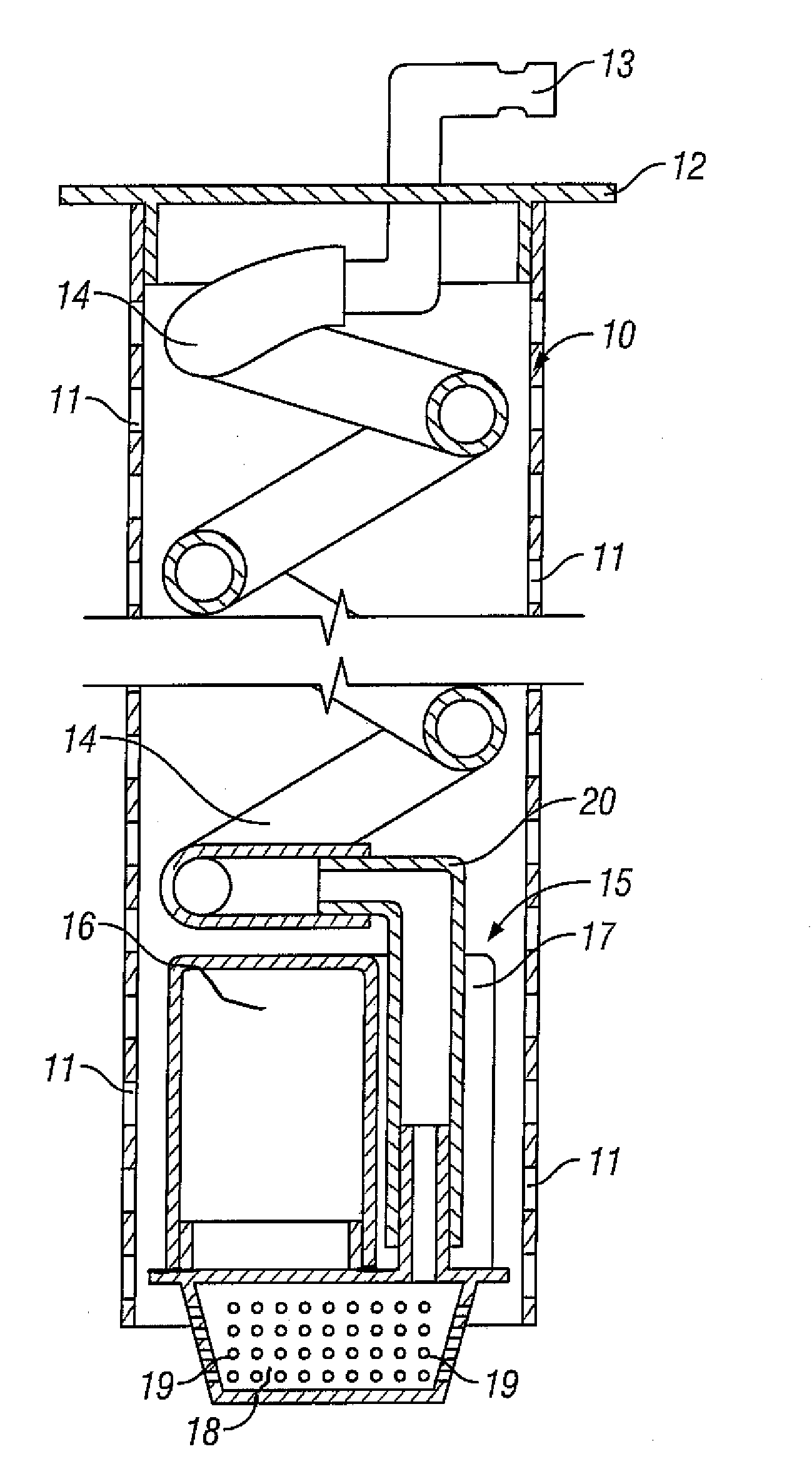
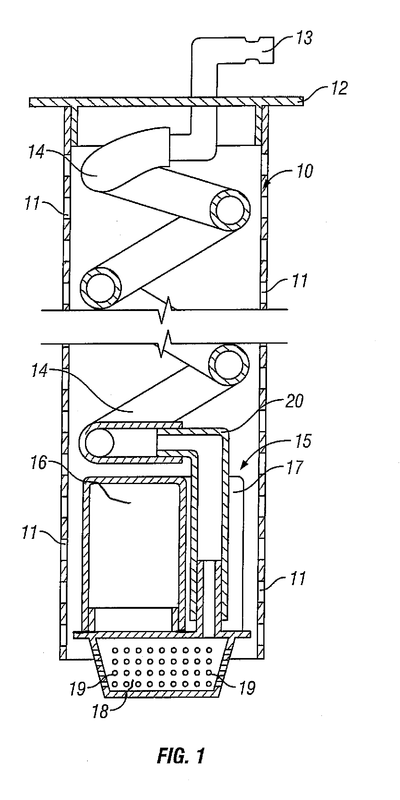
[0021]Referring to FIG. 1, there is shown a float device for fitting to a circular aperture formed in the top wall of a fuel tank (not shown). The device comprises an elongate circular-section of filter in the form of a metal sleeve 10 provided with an array of apertures 11. The sleeve 10 is open at its lower end and closed at its upper end by a flanged end cap 12, which is arranged for securing around its periphery to the edges of the aperture in the fuel tank.

[0022]A rigid feed pipe 13 extends through the end cap 12, the lower end of the pipe 13 being connected to an elongate coiled flexible tube 14 of plastics material. The lower end of the flexible tube 14 is connected to a float 15 by means of a tubular connector 20.

[0023]The float 15 is generally circular in section and is arranged to freely move vertically within the sleeve 10 with the le...


PUM

PropertyMeasurementUnit
flexibleaaaaaaaaaa
lengthaaaaaaaaaa
volumeaaaaaaaaaa

Abstract

A float device for use in drawing liquids such as fuel from a tank or other reservoir is disclosed. The device comprises a float arranged for rising and falling with the level of liquid in the tank and a liquid pick-up duct, which comprises a flexible tube having its free end coupled to the float. The float is arranged for vertical movement within a filter or other member, which encloses the float and the flexible tube. The filter or other member is elongate and tubular in construction and comprises an open lower end.

Description

BACKGROUND OF THE INVENTION[0001]1. Field of the Invention[0002]This invention relates to a float device for use in drawing liquids such as fuel from a tank or other reservoir.[0003]2. Related Art[0004]In conventional fuel tanks, the fuel is drawn from a point adjacent the bottom of the tank in order to enable the pick-up of fuel even when the level of fuel in the tank is low. However, a disadvantage of this arrangement is that any water and / or sediment which has accumulated at the bottom of the tank can be drawn up with the fuel.[0005]UK Patent Number GB2 350 337B discloses a solution to this problem in the form of a float device having a float arranged for rising and falling with the level of fuel in the tank, and a fuel pick up duct which comprises a flexible tube having its free end coupled to the float, the float being arranged for vertical movement within a filter which encloses the float and the flexible tube.[0006]In use, the float ensures that the fuel entry or pick-up end ...

Claims


Application Information

Patent Timeline
Patent Type & Authority Applications(United States)
IPC IPC(8): B60K15/077
CPCB60K15/061B60K15/077B60K2015/03236B60K2015/03473B60K2015/0772Y10T137/86252Y10T137/86212Y10T137/0318Y10T137/7323Y10T137/86348E04H4/1263B01D35/05
Inventor JAMES, MICHAEL JOHN
Owner FUEL ACTIVE LTD
Why Eureka
Try Eureka