Head-mounted display

a display and head mount technology, applied in the field of head mount displays, can solve the problems of inability to achieve the commercialization of hmds, the difficulty of downsizing hmds is the most problematic, and the design and fashion of hmds are inferior

Inactive Publication Date: 2010-07-01
SCALAR CORP
View PDF7 Cites 26 Cited by
  • Summary
  • Abstract
  • Description
  • Claims
  • Application Information

AI Technical Summary

Benefits of technology

[0013]As described above, while being useful also in the attachment-type (or later-attachment-type) head mount display, provision of the nose pad to the head mount display is useful in a product of a type in which the head mount display is not detachable to the attachment member, in other words, the head mount display is fixedly attached to the attachment member. For example, when multiple types of attachment members each having an eyeglass shape are prepared, and a head mount display provided with a nose pad is fixed to each of the attachment members, the attachment members can be easily designed.
[0023]The attachment member may be provided with temples, and the temples may be formed as straight temples. An attachment member constituted in a shape of eyeglasses includes temples as those of eyeglasses in many cases. Most general temples provided to the eyeglasses are bent downward such that leading end parts (end covers) thereof are easily fitted to the ears as seen from the lateral direction. However, there are provided temples of a type in which the end covers are bent little downward. The temples are referred to as the straight temples. When the straight temples are provided as the temples of the attachment member, the following advantage can be obtained. That is, when the head mount display is attached to the attachment member, the attachment member is separated from the face as described above. When the head mount display is detached from the attachment member, the attachment member comes close to the face. When the attachment member moves in the fore-and-aft direction as described above, the end covers of the temples and the ears of the user interfere with each other, with the end covers of the temples being bent. When the straight temples are provided as the temples, such a situation can be avoided. Thus, excellent feel of use is provided to the user.
[0027]For example, in the head mount display of the present invention, when the user wears the attachment member, the display means and the light guide means may be connected to each other while aligning in a lateral direction as seen from the user. The head mount display in which the display means and the light guide means are arranged while aligning in the lateral direction as seen from the user during use can be wholly hidden on the inner side of the attachment member when being arranged on the inner side of the attachment member (on the rear of the eyeglass lenses when the attachment member is eyeglasses). As a result, it is possible to substantially avoid the head mount display from being exposed on the upper and lower sides of the attachment member. This is advantageous in sophisticating design and fashion of the head mount display.
[0029]Examples of the available light guide means include free-form surface prisms in each of which the image (image light for displaying the image) is reflected by a predetermined number of times so as to be guided to the eye of the user. With use of the free-form surface prisms, it is possible to easily achieve downsizing of the whole of the head mount display. Each of the free-form surface prisms may have four surfaces constituted by a first surface, a second surface, a third surface, and a fourth surface, in which the light from the display means is passed through the first surface, the light having been passed through the first surface is reflected by the second surface, the light having been reflected by the second surface is reflected by the third surface, and the light having been reflected by the third surface is passed through the fourth surface so that the light guided into the insides thereof is changed in direction and the image displayed on the display means is enlarged. Note that, while the first through fourth surfaces in this case may not be continuous with each other, at least two of the first through fourth surfaces (second and fourth surfaces, for example) may be smoothly continuous with each other so as to constitute one surface. As a matter of course, the light guide means are not limited to the free-form surface prisms, and each may be constituted by an optical element having a function of changing the direction of the image light for displaying the image (for example, this is achieved by a reflecting mirror) and a function of enlarging the image (for example, this is achieved by a lens). In this case, the light guide means may be constituted by combination of multiple optical elements.
[0031]Further, the head mount display may further include an adjustment mechanism for enabling the display means to move in a direction of the light guide means. With this configuration, by optimizing the distance between the display means and the light guide means in accordance with the user's eyesight, it is possible to provide an image subjected to eyesight correction to the user.

Problems solved by technology

However, for example, at the time of being located in front of the eyeglass lenses, the HMD is inferior in terms of design and fashion.
In the case of arranging the HMD on the inner side of the attachment member, difficulty in downsizing the HMD is most problematic.
However, under the present circumstances, needless to say that commercialization of the HMDs has not been achieved yet, even prototypes thereof have not been satisfactorily completed yet.
To that extent, it is difficult to downsize the HMDs and reduce the fore-and-aft thickness thereof (corresponding to the fore-and-aft direction of the user's face in the case where the HMD is mounted to the user's head, which is the same in the subject application).
In such a case, a nose pad is problematic.
This is because, in many cases, while the attachment member is provided with a nose pad similar to that of normal eyeglasses for the purpose of being fixed to the user's head, the nose pad becomes useless when the attachment member gets away from the user's face, with the result that it is difficult to fix the attachment member to the user's head.

Method used


Image

  • Head-mounted display
  • Head-mounted display
  • Head-mounted display

Examples


Embodiment Construction

[0045]In the following, a preferred embodiment of the present invention is described in detail with reference to figures.

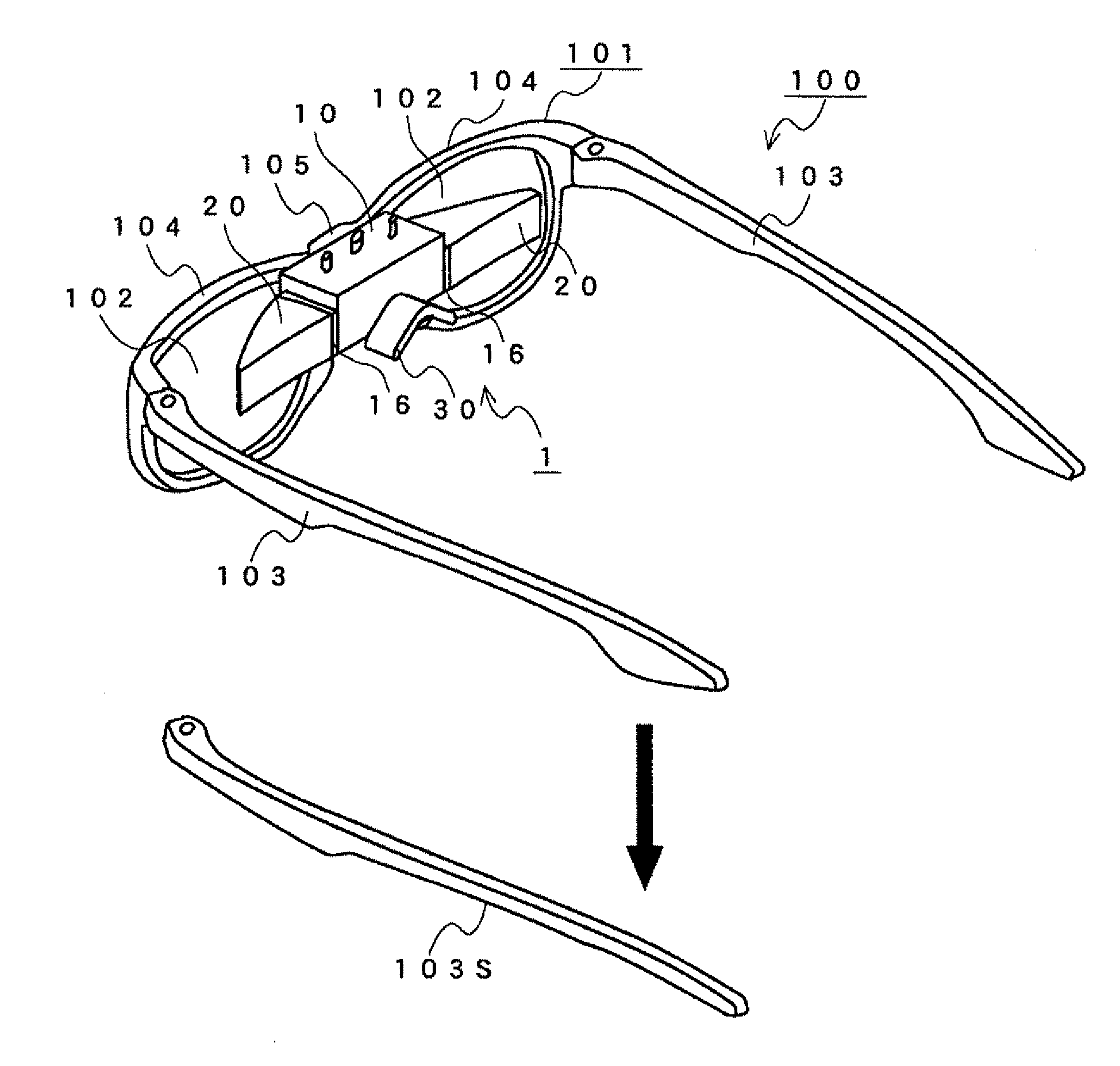
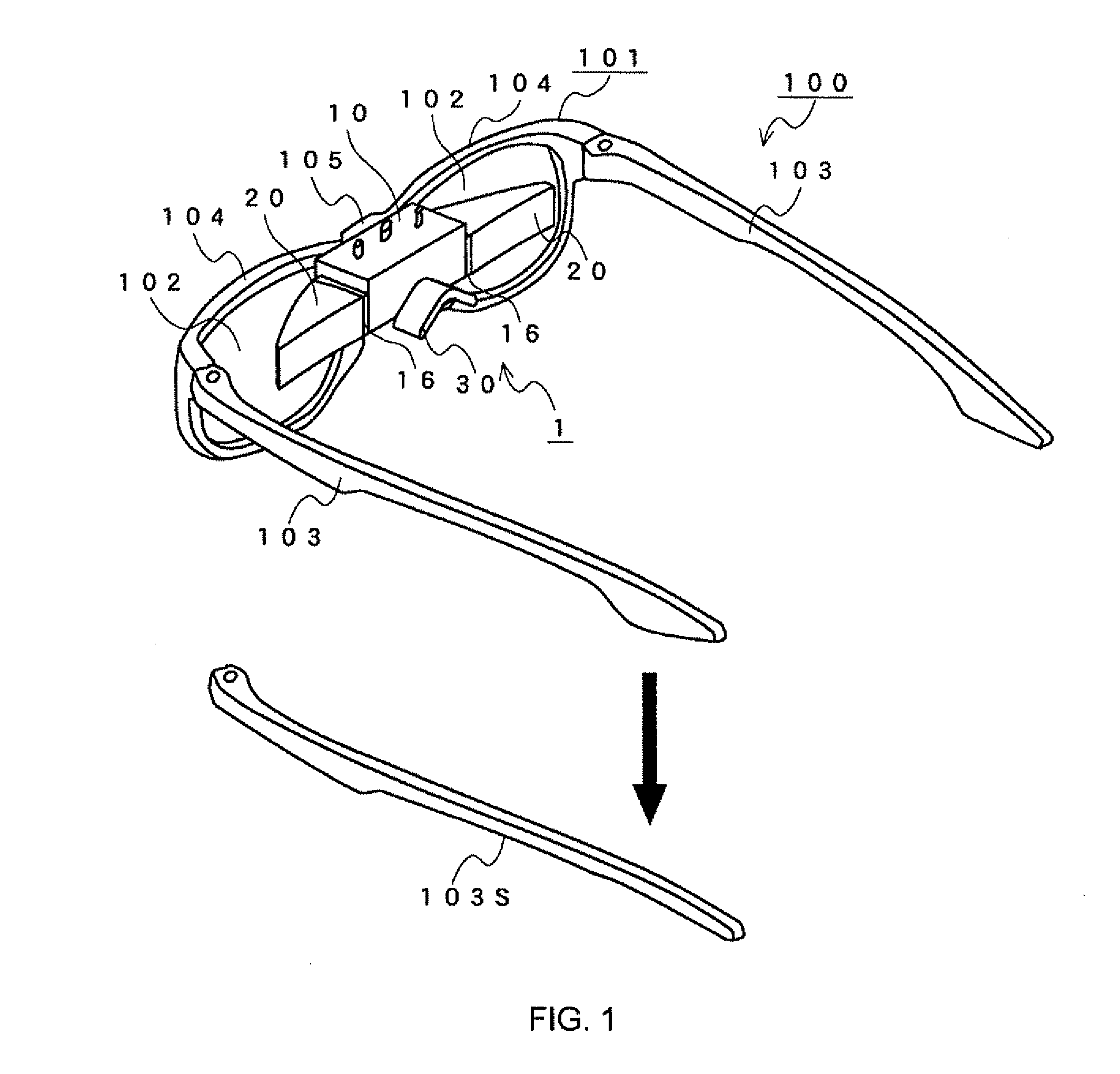
[0046]A head mount display 1 in this embodiment is an attachment-type HMD used while being attached to eyeglasses 100 having an eyeglass frame shape as illustrated in FIG. 1. In this embodiment, the head mount display 1 is attached on the rear of the eyeglasses 100. During use, the head mount display 1 is situated in a space between the user's face and the eyeglasses 100. Therefore, those other than the user are less likely to find the presence of the head mount display 1.

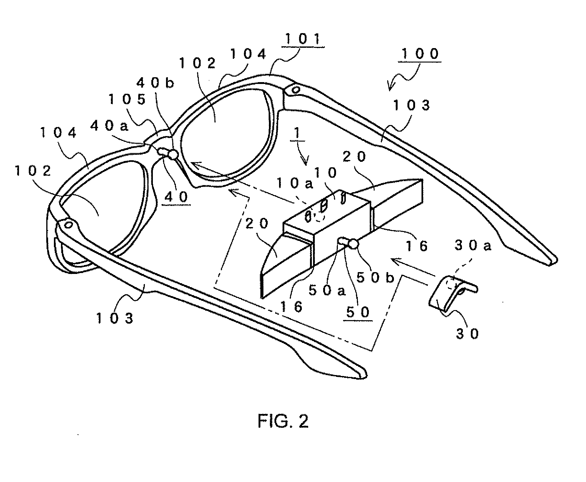
[0047]The eyeglasses 100 correspond to an attachment member of the present invention, and has the same structure as that of conventional pairs of eyeglasses, in which eyeglass lenses 102 are fitted to an eyeglass frame 101. Note that, the eyeglass lenses 102 may be prescribed or unprescribed, and may be transparent-and-colorless or transparent-and-colored. The eyeglass frame 101 is provided with ...


PUM


Abstract

Provided is a head mount display of a type of being attached to eyeglasses. The head mount display (1) includes a case (10) incorporating a display and free-form surface prisms (20). A nose pad (30) is attached to the case (10) of the head mount display (1). The head mount display (1) is used with the case (10) being attached to a bridge (105) of eyeglasses (100). On such an occasion, the nose pad (30) attached to the case (10) functions as the nose pad for the eyeglasses (100).

Description

TECHNICAL FIELD[0001]The present invention relates to a head mount display used while being mounted to a user's head.BACKGROUND ART[0002]A head mount display, which is mounted to a part of a body such as a head during use, for displaying an image in front of the user's eyes, is used in various fields for displaying an image, which includes a field of virtual reality. Generally, the head mount display is formed into a goggle-like shape or into a large eyeglass-frame shape. Further, there is also available a head mount display of a type which is detachable to an attachment member having an eyeglass-frame shape and used while being attached to the attachment member (hereinafter, referred to as “attachment-type head mount display (HMD)”). The attachment member in this case includes a commercially available eyeglasses.[0003]Examples of the attachment-type HMD include one adopting a type of being attached to the outer side of the attachment member (a part father from the user's head with ...

Claims


Application Information

Patent Timeline
Patent Type & Authority Applications(United States)
IPC IPC(8): G09G5/00
CPCG02B17/086G02B27/0172G02B2027/0132G02B2027/0158G02B2027/0178G02B27/01
Inventor YAMAMOTO, MASAO
Owner SCALAR CORP
Why Eureka
Try Eureka