Liquid ejection apparatus

a technology of liquid ejection and waste tank, which is applied in the direction of printing, other printing apparatus, etc., can solve the problem of possible leakage of the waste tank to the outside of the tank

Active Publication Date: 2010-07-01
BROTHER KOGYO KK
View PDF3 Cites 10 Cited by
  • Summary
  • Abstract
  • Description
  • Claims
  • Application Information

AI Technical Summary

Benefits of technology

[0009]According to the present invention, it is possible to cure liquid discharged to the waste tank. This makes it possible to prevent the liquid in the waste tank from leaking to the outside, for example when carrying the liquid ejection apparatus.

Problems solved by technology

In the case where the waste tank reserves ink therein, the ink in the waste tank possibly leaks to the outside, for example when carrying the ink jet printer.

Method used


Image

  • Liquid ejection apparatus
  • Liquid ejection apparatus
  • Liquid ejection apparatus

Examples


Embodiment Construction

[0025]The following describes a preferred embodiment of the present invention.

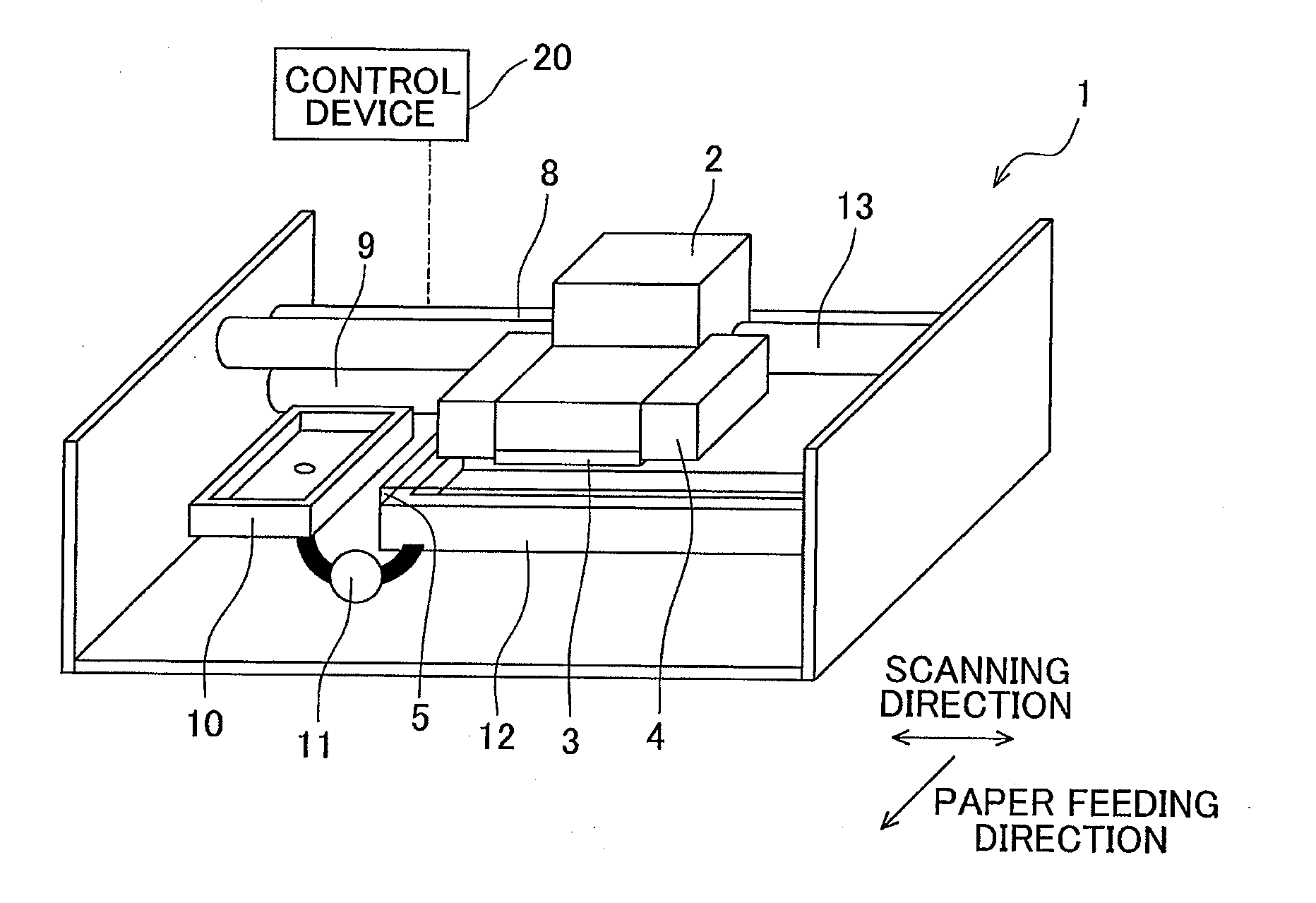
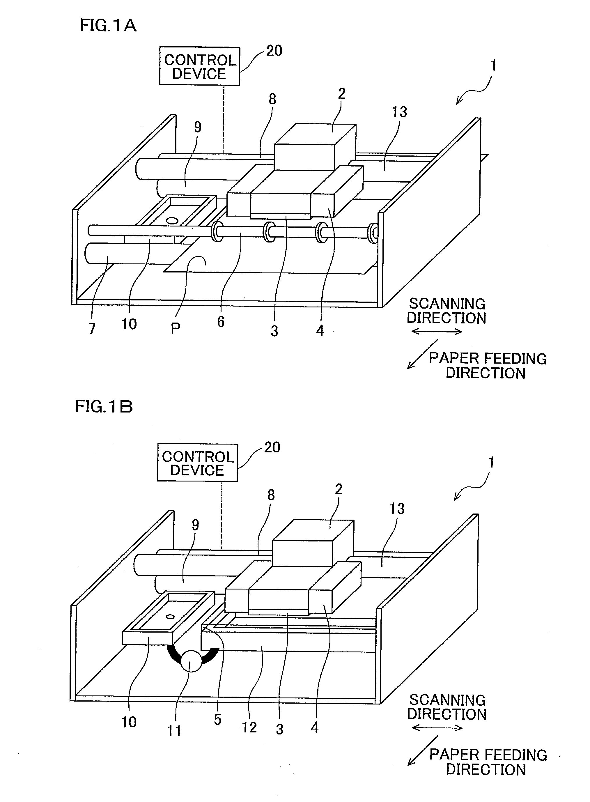
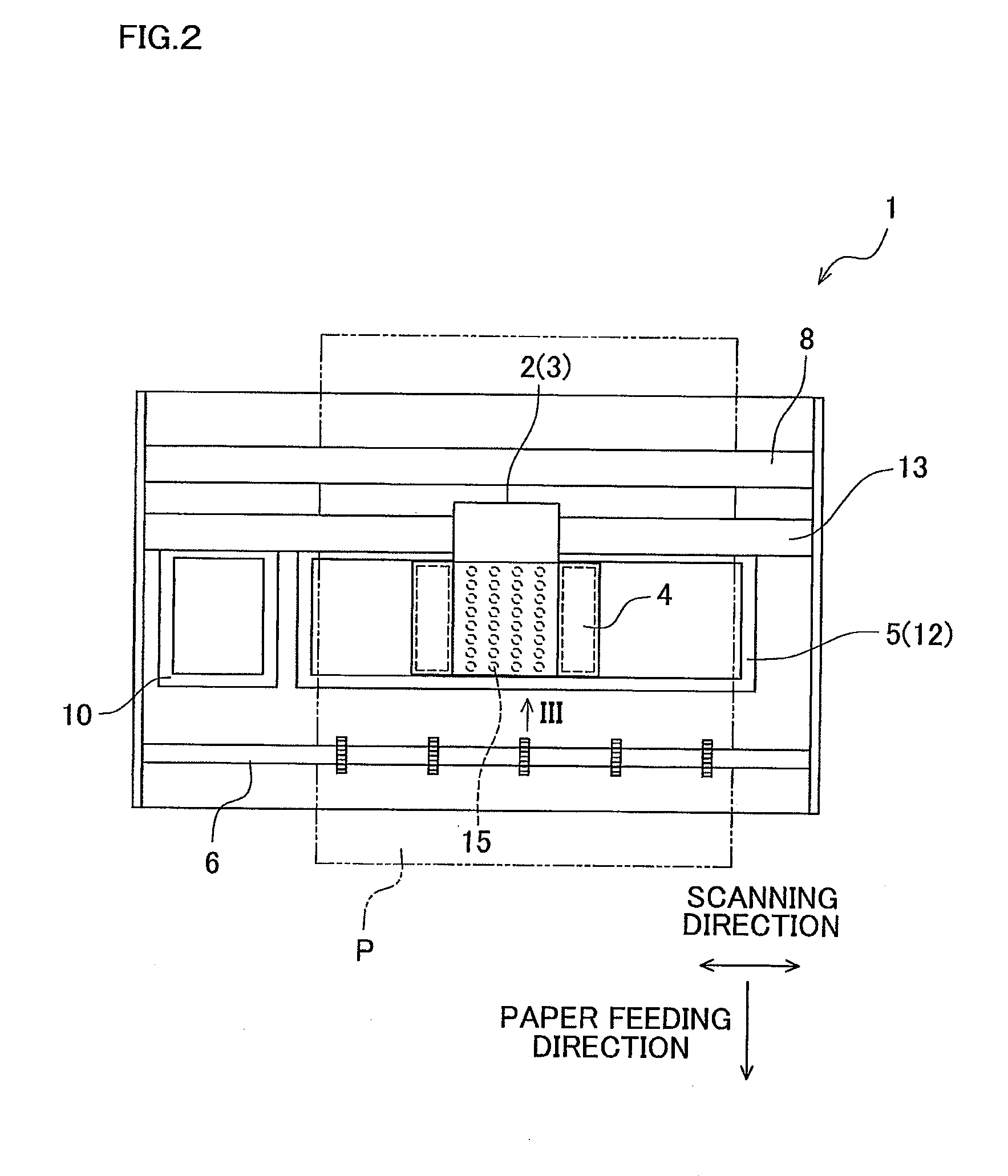
[0026]FIG. 1A is a schematic diagram of a printer of this embodiment, with a recording sheet P placed on a later-described platen 5. FIG. 1B is a schematic diagram of the printer of this embodiment, without a recording sheet P placed on the platen 5. FIG. 2 is a plan view of FIGS. 1A, 1B. FIG. 3A is a diagram of the printer of FIG. 2 which performs a printing process (will be described later), viewed from a direction of an arrow III in FIG. 2. FIG. 3B is a diagram of the printer of FIG. 2 which performs a process of applying ultraviolet light to a later-described waste tank 12, viewed from the direction of the arrow III in FIG. 2. Note that in FIG. 1B, later-described conveyor rollers 6 and 7 are omitted.

[0027]A printer 1, which is a liquid ejection apparatus, is a portable printer of relatively small size. As shown in FIGS. 1A, 1B, 2, 3A, and 3B, the printer 1 includes: a carriage 2; an ink-jet head 3 whi...


PUM


Abstract

A liquid ejection apparatus includes: a liquid ejection head which ejects photo-curable liquid from nozzles; a first light applicator which applies light to an ejection target having received liquid ejected by the liquid ejection head; a waste tank which reserves therein liquid discharged from the liquid ejection head; and a second light applicator which applies light to liquid in the waste tank.

Description

CROSS REFERENCE TO RELATED APPLICATION[0001]The present application claims priority from Japanese Patent Application No. 2008-334818, which was filed on Dec. 26, 2008, the disclosure of which is herein incorporated by reference in its entirety.BACKGROUND OF THE INVENTION[0002]1. Field of the Invention[0003]The present invention relates to a liquid ejection apparatus which ejects photo-curable liquid from nozzles.[0004]2. Description of Related Art[0005]In an ink jet printer having an ink jet head and a UV (ultraviolet) light source unit which are carried on a carriage reciprocating along a guide rod in a scanning direction, it has been known that printing on a recording medium is conducted in the following manner: UV curable ink is ejected onto the recording medium from the ink jet head which reciprocates with the carriage in the scanning direction, so that the ejected ink is landed on the recording medium; and the ink landed on the recording medium is cured by ultraviolet light app...

Claims


Application Information

Patent Timeline
Patent Type & Authority Applications(United States)
IPC IPC(8): B41J2/165
CPCB41J2/16532B41J2/1721B41J11/002B41J29/38B41J11/00214
Inventor SUGAHARA, HIROTO
Owner BROTHER KOGYO KK
Why Eureka
Try Eureka