Electrode junction structure and manufacturing method thereof

a technology of junction structure and manufacturing method, which is applied in the direction of identification means, instruments, chemistry apparatus and processes, etc., can solve the problems of inability to reduce the area described above, and achieve the effect of preventing stress concentration, preventing defects from being caused, and easy curved

Inactive Publication Date: 2010-07-01
PANASONIC CORP
View PDF3 Cites 8 Cited by
  • Summary
  • Abstract
  • Description
  • Claims
  • Application Information

AI Technical Summary

Benefits of technology

[0041]According to the electrode junction structure and the method for manufacturing the electrode junction structure according to the present invention, the edge of the sealing resin or the predetermined portion is, in the planar view, formed so that the edge has a consecutive waveform portion in which the convex portion and the concave portion alternate with the imaginary line parallel to the edge of the glass substrate and located outer than the edge of the glass substrate as a center axis, and so that the convex portions are located on the flexible substrates. Therefore, when an external force is applied to the flexible substrates, stress concentration can be prevented to thus prevent defects from being caused.
[0042]Furthermore, according to the electrode junction structure and the method for manufacturing the electrode junction structure according to the present invention, the convex portions are made to be located on the flexible substrates. Therefore, as compared with the second conventional example, the flexible substrates can be more easily curved. Thus, the area of the sealing resin and flexible substrates can be reduced in the planar view.
[0043]Moreover, according to the method for manufacturing the electrode junction structure according to the present invention, the formation of the sealing resin by application is carried out after carrying out in advance the treatment of cleaning the predetermined portion to improve the wettability. Therefore, the formation of the sealing resin by application is made easier.

Problems solved by technology

Therefore, in the electrode junction structure according to the second conventional example, it is difficult to curve a portion of the flexible substrate 102 covered with the sealing resin 104, resulting in the problem that an area described above is not able to be reduced.

Method used


Image

  • Electrode junction structure and manufacturing method thereof
  • Electrode junction structure and manufacturing method thereof
  • Electrode junction structure and manufacturing method thereof

Examples


first embodiment

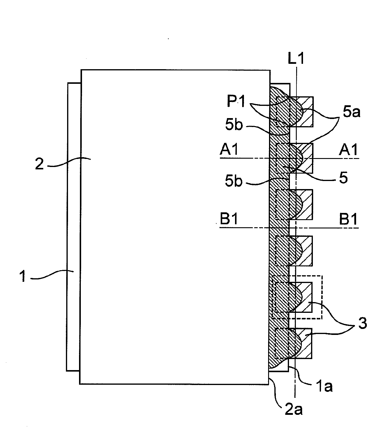
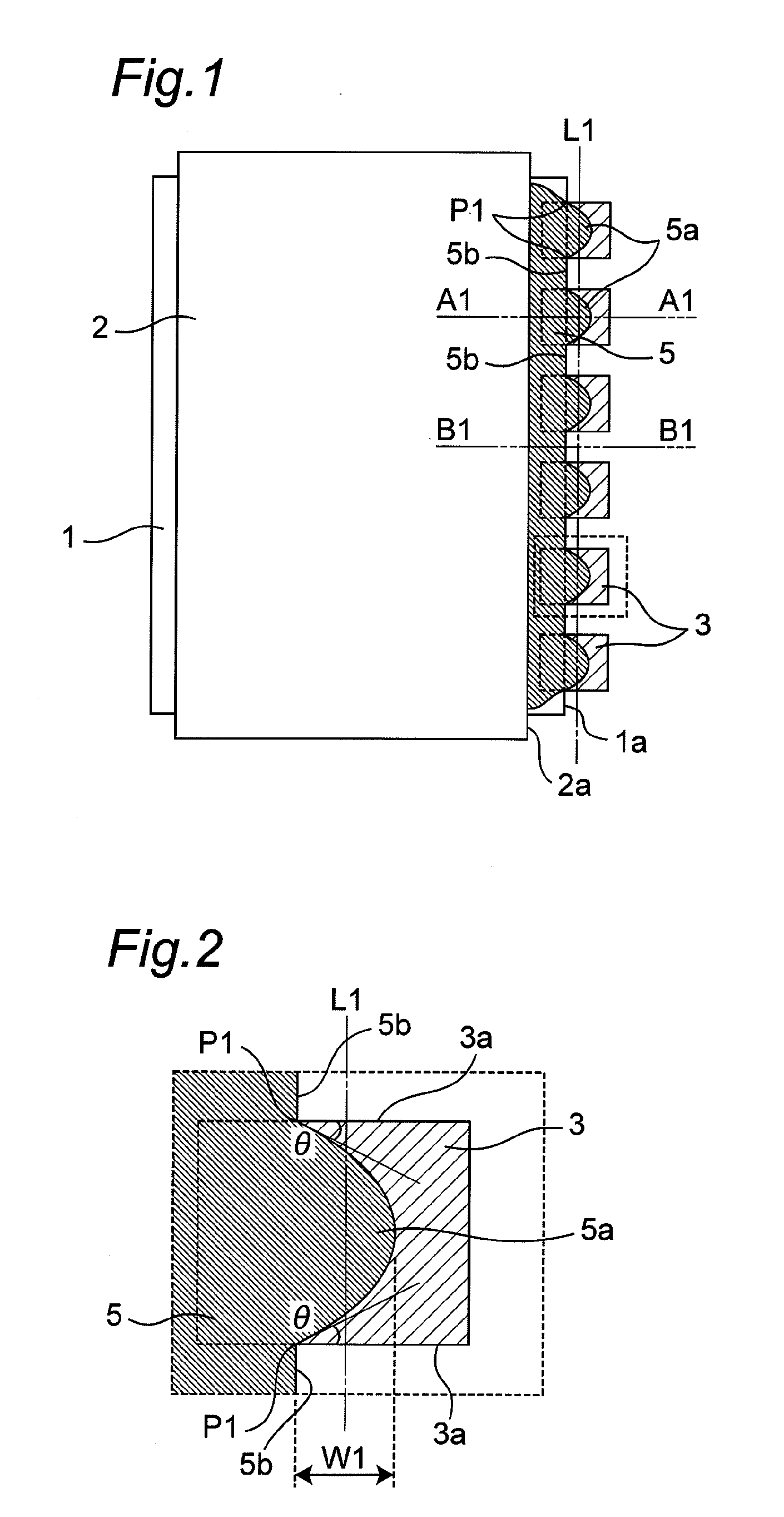
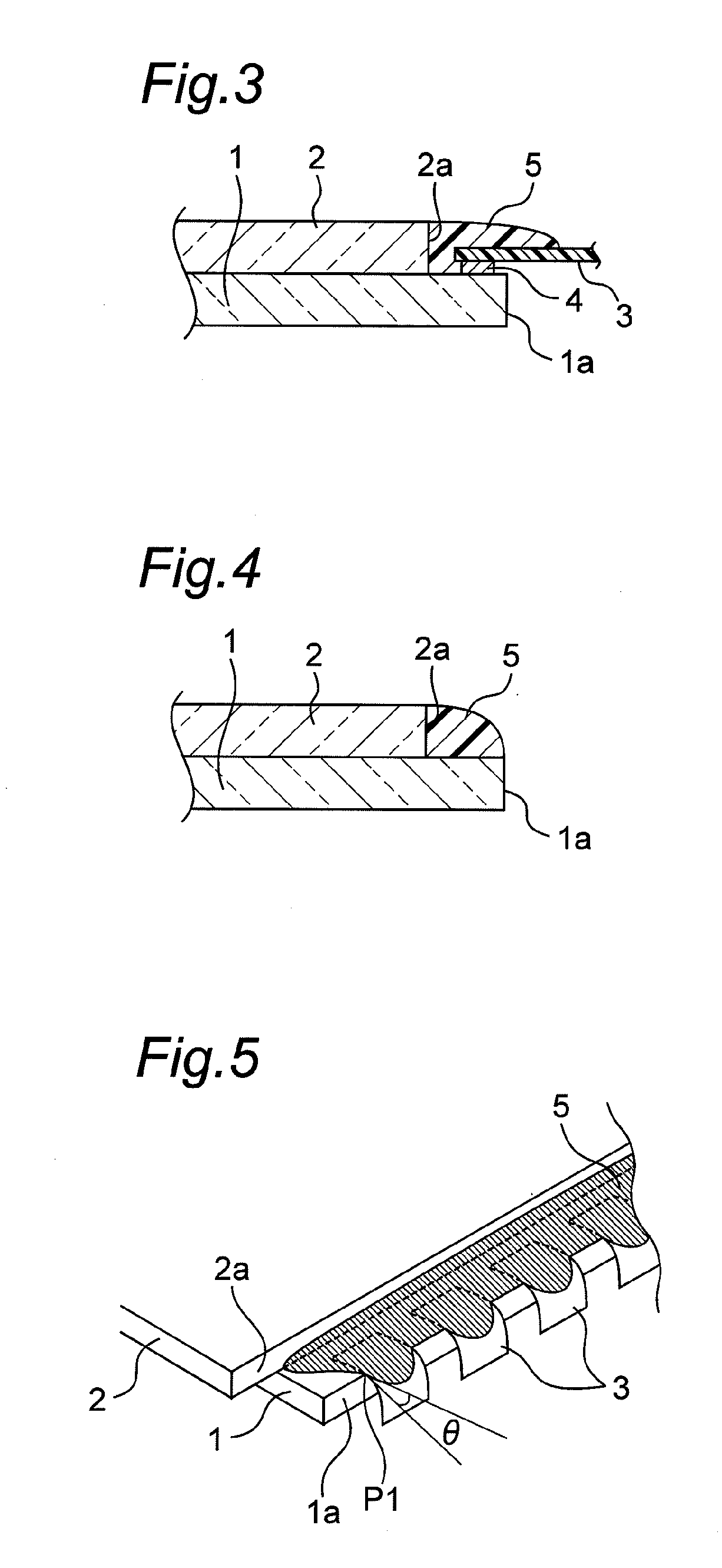
[0089]FIG. 1 is a plan view illustrating a configuration of an electrode junction structure according to a first embodiment of the present invention. FIG. 2 is an enlarged plan view of a portion surrounded by a dotted line in FIG. 1. FIG. 3 is a cross-sectional view of FIG. 1 along a line A1-A1, and FIG. 4 is a cross-sectional view of FIG. 1 along a line B1-B1. FIG. 5 is a perspective view of the electrode junction structure of FIG. 1. The electrode junction structure according to the first embodiment is to be used for PDPs.

[0090]In FIG. 1, the electrode junction structure according to the first embodiment has a rectangular first glass substrate 1, a rectangular second glass substrate 2 placed to be opposed to the first glass substrate 1, and a plurality of rectangular flexible substrates 3 joined to the first glass substrate 1.

[0091]One of the first glass substrate 1 and the second glass substrate 2 is a front panel for a PDP, whereas the other is a back panel for a PDP. The first ...

second embodiment

[0113]FIG. 10 is a plan view illustrating an electrode junction structure according to a second embodiment of the present invention. FIG. 11 is an enlarged plan view of a portion surrounded by a dotted line in FIG. 10. The electrode junction structure according to the second embodiment differs from the electrode junction structure according to the first embodiment described above in that the convex portion 5a of the sealing resin 5 is formed to have two mountain shapes with an inwardly recessed portion 5c.

[0114]The formation of the recessed portion 5c in the convex portion 5a can prevent stress concentration to prevent defects from being caused when an external force is applied to the flexible substrates 3, and makes it easier to curve the flexible substrates 3 as compared with the first embodiment described above. Thus, the area of the sealing resin 5 and flexible substrates 3 in the planar view can be reduced more than in the first embodiment described above.

third embodiment

[0115]FIG. 12 is a plan view illustrating an electrode junction structure according to a third embodiment of the present invention. FIG. 13 is an enlarged plan view of a portion surrounded by a dotted line in FIG. 12. The electrode junction structure according to the third embodiment differs from the electrode junction structure according to the first embodiment described above in that the flexible substrate 3 is provided with two strip-shaped slits 3b and the convex portion 5a of the sealing resin 5 is formed to have three mountain shapes with two inwardly recessed portion 5c.

[0116]Providing the flexible substrates 3 with the slits 3b in a direction perpendicular to the edge 1a of the first glass substrate 1 makes it much easier to curve the flexible substrates 3. Furthermore, forming the convex portion 5a with the recessed portions 5c so as to avoid the slits 3b can prevent stress concentration to prevent defects from being caused when an external force is applied to the flexible...


PUM

PropertyMeasurementUnit
distanceaaaaaaaaaa
distanceaaaaaaaaaa
thicknessaaaaaaaaaa

Abstract

The electrode junction structure includes: a glass substrate; a plurality of flexible substrates, in a planar view, arranged to cross over an edge of the glass substrate and arranged to have a space from each other along the edge; an adhesive for joining the glass substrate and each flexible substrate; and a sealing resin for covering junction portions between the glass substrate and each flexible substrate, wherein an edge of the sealing resin is formed so that the edge of the sealing resin has, in the planar view, a consecutive waveform portion in which a convex portion and a concave portion alternate with an imaginary line as a center axis, the imaginary line being parallel to the edge of the glass substrate and locating outer than the edge of the glass substrate, and wherein the convex portions are formed to be located on the flexible substrates.

Description

BACKGROUND OF THE INVENTION[0001]The present invention relates to an electrode junction structure in which electrodes formed on a glass substrate and electrodes formed on flexible substrates are electrically joined with an adhesive, and in which junction portions between glass substrate and flexible substrate are covered with a sealing resin so as not to be exposed to outside, and a method for manufacturing the electrode junction structure.[0002]Conventionally, this type of electrode junction structure is known to have various types of structures. For example, conventional electrode junction structures include structures shown in FIGS. 26 and 27. FIG. 26 is a plan view of an electrode junction structure according to a first conventional example, and FIG. 27 is a cross-sectional view of a portion of the electrode junction structure according to the first conventional example.[0003]The electrode junction structure according to the first conventional example has a rectangular glass sub...

Claims


Application Information

Patent Timeline
Patent Type & Authority Applications(United States)
IPC IPC(8): H01R9/22B32B38/16G09F9/00H05K1/14H05K3/36
CPCH01R13/52H05K1/142H05K3/284H05K3/361H05K2201/10977
Inventor KUMAZAWA, KENTAROONO, MASAHIROTOMURA, YOSHIHIRO
Owner PANASONIC CORP
Why Eureka
Try Eureka