Wireless communication apparatus and wireless communication method

Inactive Publication Date: 2010-07-01
FUJITSU TOSHIBA MOBILE COMM LTD
View PDF5 Cites 12 Cited by
  • Summary
  • Abstract
  • Description
  • Claims
  • Application Information

AI Technical Summary

Benefits of technology

[0014]Therefore, the present invention can provide a wireless communication apparatus and a wireless communication method wherein even in the case of using two discrete frequencies as a single system band, good transmission power contro

Problems solved by technology

However, these are almost common with respect to the distance loss and shadowing loss.
In this case, since the measured path loss and the path

Method used


Image

  • Wireless communication apparatus and wireless communication method
  • Wireless communication apparatus and wireless communication method
  • Wireless communication apparatus and wireless communication method

Examples


first embodiment

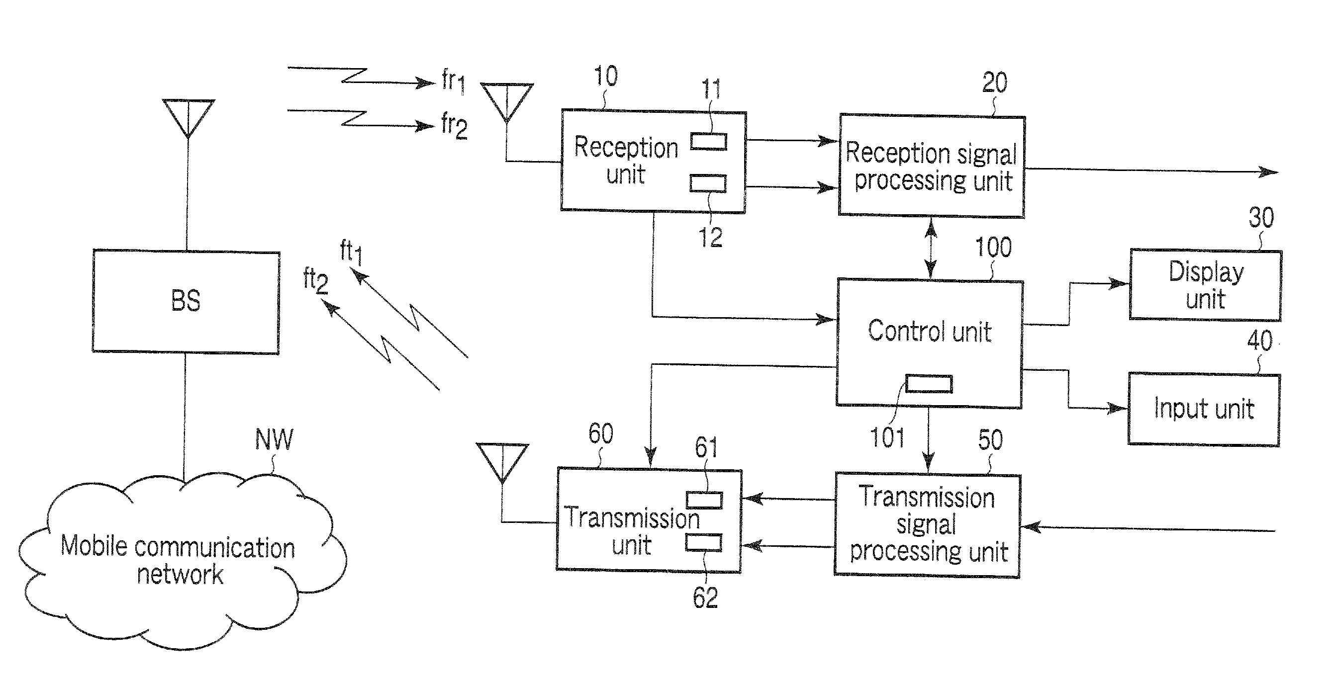
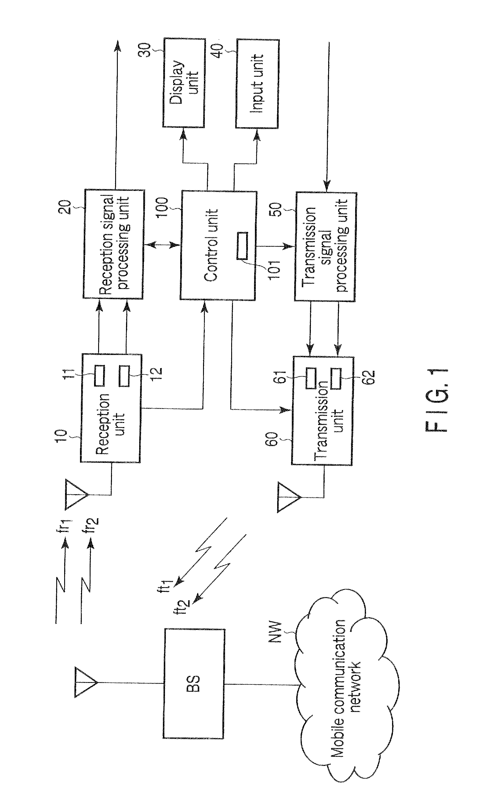
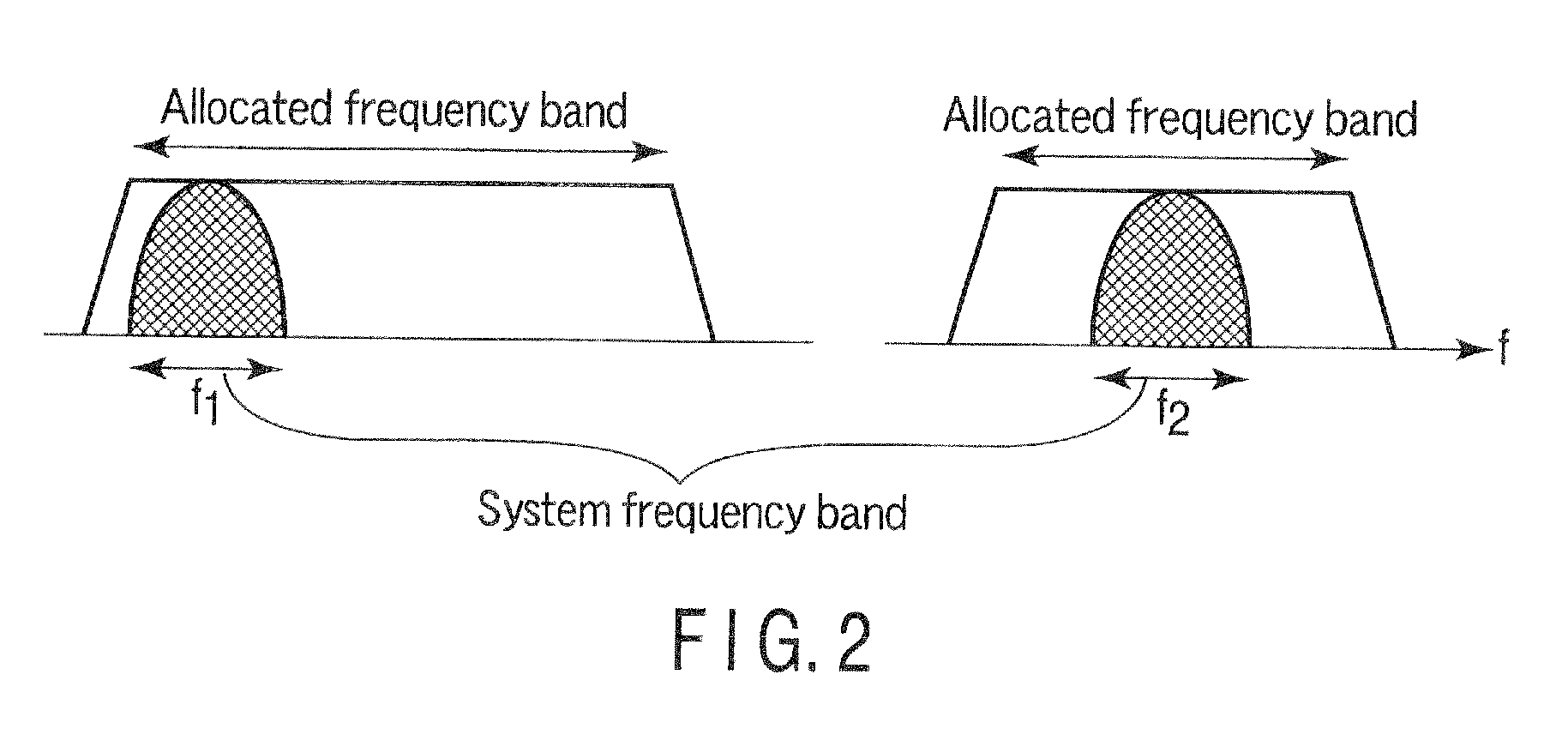
[0020]FIG. 1 Shows the structure of a mobile wireless terminal, apparatus according to a first embodiment of the present invention. This mobile wireless terminal apparatus is a mobile station of a cellular system according to the 3GPP IMT advanced Workshop REV-080058 Summary of LTE Advanced Requirements presented at the workshop (April 2008). As shown on FIG. 2, in two allocated frequency bands, two frequency bands f1 and f2 for use are utilized as a single system band. Specifically, a mobile wireless terminal apparatus and a base station apparatus BS execute communication by making use of two frequency bands as a single system band in each of an uplink and a downlink.

[0021]As shown in FIG. 1, the mobile wireless terminal apparatus includes a reception unit 10, a reception signal processing unit 20, a display unit 30, an input unit 40, a transmission signal processing unit 50, a transmission unit 60 and a control unit 100.

[0022]The reception unit 10 includes two receivers 11 and 12 ...

second embodiment

[0043]Next, a mobile wireless terminal apparatus according to a second embodiment of the present invention is described. The apparent structure of the mobile wireless terminal apparatus according to this embodiment is substantially the same as that of the mobile wireless terminal apparatus shown in FIG. 1, so only differences from the first embodiment are mainly described with reference to FIG. 1.

[0044]The mobile wireless terminal apparatus according to the second embodiment executes a closed-loop transmission power control. Thus, the base station apparatus BS receives signals of two frequencies ft1 and ft2 from the mobile wireless terminal apparatus, and measures the power levels thereof. On the basis of the measurement result, the base station apparatus BS sends to the mobile wireless terminal apparatus TPC (Transmit Power Control) commands for controlling the transmission power levels, so that the reception power level of each frequency band in the base station apparatus BS may f...


PUM


Abstract

A reception unit measures a reception power level of a reference signal which is received from a base station apparatus BS. A reception signal processing unit acquires information indicative of a transmission power level of the reference signal. A control unit finds a path loss on the basis of the reception power level and this information. The control unit determines, on the basis of the path loss, a transmission power level of that one of two transmission frequency bands, which is closer to a frequency band with respect to which the pass loss has been measured. The control unit determines a transmission power level of the other transmission frequency band, which is farther from the frequency band with respect to which the pass loss has been measured, by correcting the transmission power level on the basis of a correction value based on a difference in frequency.

Description

CROSS-REFERENCE TO RELATED APPLICATIONS[0001]This application is based upon and claims the benefit of priority from prior Japanese Patent Application No. 2008-330843, filed Dec. 25, 2008, the entire contents of which are incorporated herein by reference.BACKGROUND OF THE INVENTION[0002]1. Field of the Invention[0003]The present invention relates to a wireless communication apparatus which is used, for example, in a cellular system.[0004]2. Description of the Related Art[0005]As is well known, in a mobile communication system such as a cellular system, the transmission power of a wireless communication apparatus is controlled. In general, the transmission power control aims at setting the reception quality at a desired value. In the transmission power control of a mobile wireless terminal apparatus in the cellular system, the reception quality in a base station apparatus is made to fall within a desired range.[0006]The transmission power control is determined by a propagation loss (p...

Claims


Application Information

Patent Timeline
IPC IPC(8): H04B17/00
CPCH04W52/242
Inventor ASANUMA, YUTAKA
Owner FUJITSU TOSHIBA MOBILE COMM LTD
Why Eureka
Try Eureka