Guardrail Post Base

a post base and guardrail technology, applied in the direction of fencing, ways, buildings, etc., can solve the problems of requiring a relatively large amount of time, affecting the safety of workers and equipment, and reducing the service life of workers, so as to achieve convenient installation and save time and money.

Inactive Publication Date: 2010-07-08
WEBSTER IV EUGENE P
View PDF18 Cites 20 Cited by
  • Summary
  • Abstract
  • Description
  • Claims
  • Application Information

AI Technical Summary

Benefits of technology

[0006]Accordingly, the invention presents a support base that is rugged and easy to install, thereby saving time and money. The invention provides for improved elements thereof in an arrangement for the purposes described that are inexpensive, dependable and fully effective in accomplishing their intended purposes.

Problems solved by technology

Heretofore, erecting these temporary barriers has required a relatively great deal of time and such barriers have afforded less than adequate protection for the working personnel and equipment.
This scenario often resulted in loss revenue due to equipment damage and injuries.

Method used


Image

  • Guardrail Post Base
  • Guardrail Post Base
  • Guardrail Post Base

Examples


Embodiment Construction

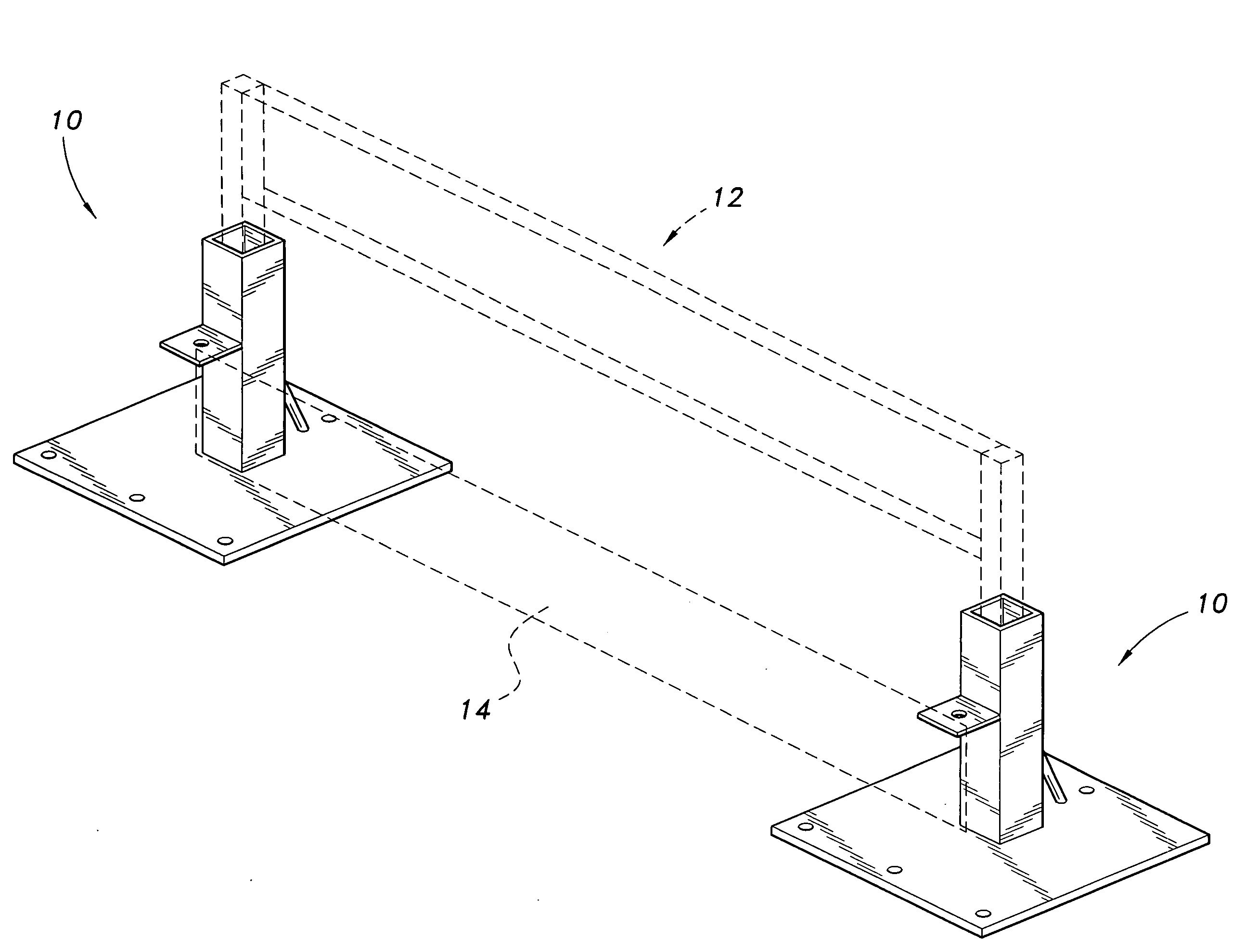
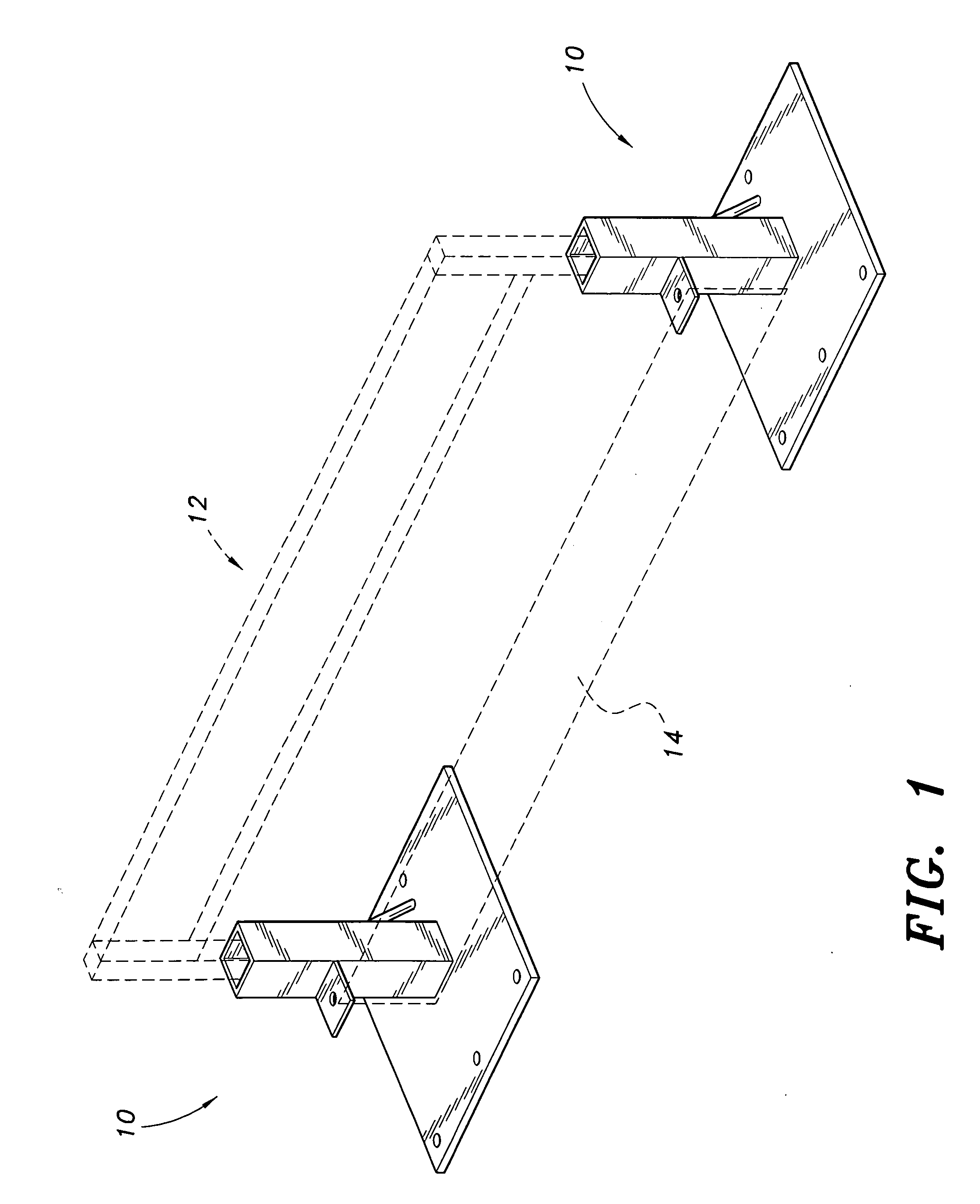
[0012]Attention is first directed to FIG. 1, wherein the guardrail post base is generally indicated at 10. A pair of post bases 10 support a post and safety rail section 12 and kick board 14 (both shown in phantom lines) thereon. Post and safety rail section 12 and kick board 14 are conventional and are not per se part of the inventive concept. As discussed above, post bases 10 are attached on the perimeter of the floor (not shown) of a building under construction. Post and safety rail section 12 is mounted in the post base to provide fall protection for personnel. Kick board 14 prevents tools from being accidentally pushed from the edge of the floor.

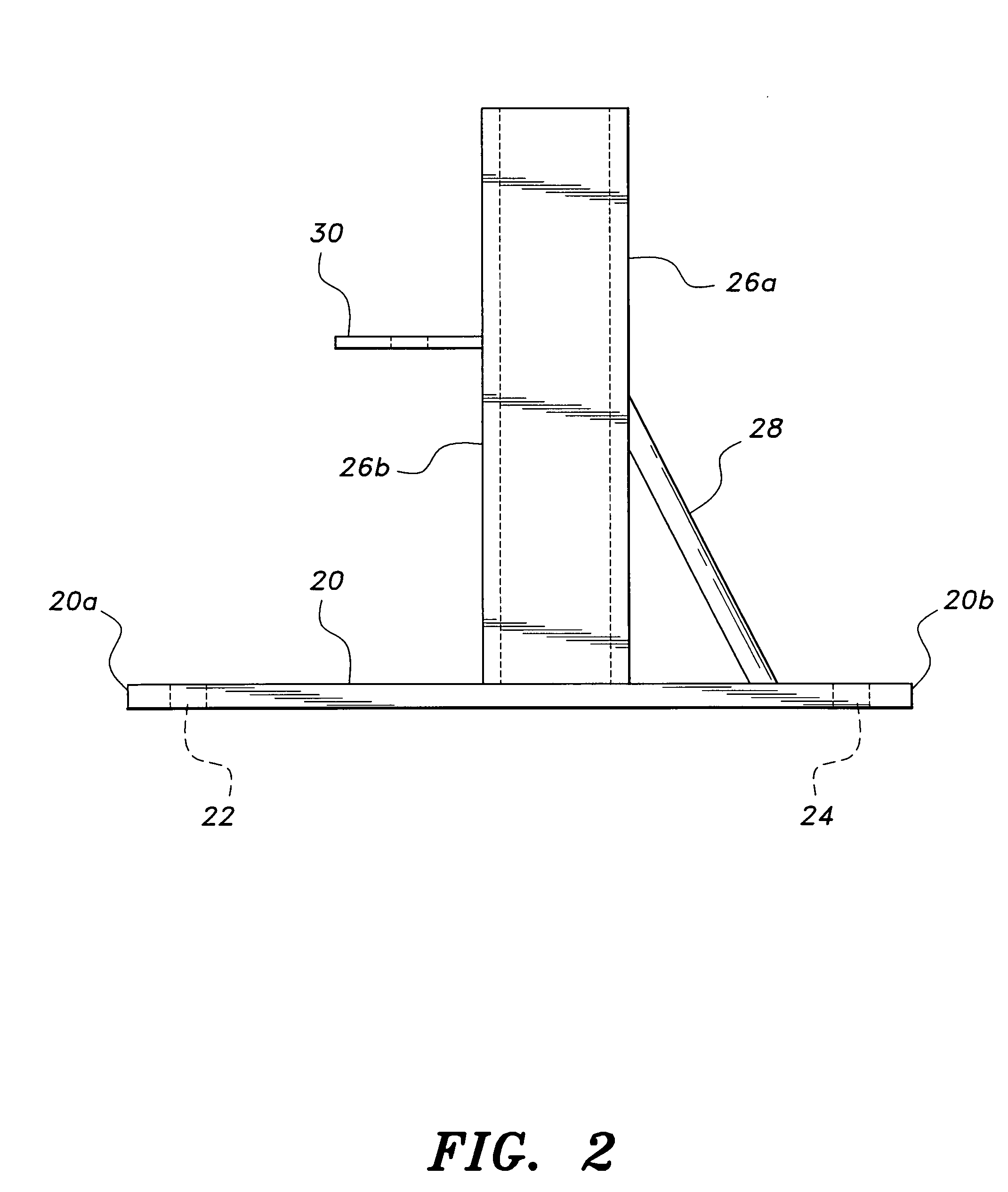
[0013]As best seen in FIGS. 2 and 3, post base 10 comprises a ¼″×8″×8″ base plate 20. A plurality of fastener holes 22 are spaced along one edge 20a of base plate 20. A single fastener hole 24 is centered on opposite edge 20b. A square, hollow tube 26 1½″×1½″ having ¼″ thick walls is centered on the upper surface of base plate 20 and at...


PUM


Abstract

The guardrail post base is designed to bolt to the plywood floor of a building under construction. The post base is provided with a tube adapted to receive conventional guardrail posts. All parts of the post base are fabricated from steel having a minimum yield stress of 36 KSI. The post base includes a plate for attaching a kick board thereto.

Description

BACKGROUND OF THE INVENTION[0001]1. Field of the Invention[0002]The present invention generally relates to support apparatus. More specifically, the present invention is drawn to a support bracket for safety barriers used at building construction sites.[0003]2. Description of the Related Art[0004]Conventionally safety barriers, including fences and / or railings, are temporary structures employed at building construction sites. The barriers are erected around the perimeter of the building floors to provide safety for the workers and also to prevent tools and other construction paraphernalia from being accidentally pushed over the edges of the floor. Usually the barriers comprise upright rods that have their lower ends received in recesses drilled or otherwise provided in the building floor. Alternatively, the upright rods are received in clamps, which clamps are mounted along the edges of the floor. Heretofore, erecting these temporary barriers has required a relatively great deal of ...

Claims


Application Information

Patent Timeline
Patent Type & Authority Applications(United States)
IPC IPC(8): E04H17/22
CPCE01F15/0461E01F15/0476E04G21/3223
Inventor WEBSTER, IV, EUGENE P.
Owner WEBSTER IV EUGENE P
Why Eureka
Try Eureka