Bi-directional bend resistor

a resistor and bi-directional technology, applied in the direction of resistors, adjustable resistors, electrical devices, etc., can solve the problem that deflectable resistors can only increase electrical resistan

Inactive Publication Date: 2010-07-08
IMAGES SCI INSTR
View PDF5 Cites 9 Cited by
  • Summary
  • Abstract
  • Description
  • Claims
  • Application Information

AI Technical Summary

Problems solved by technology

This deflectable resistor can only increase electrical resistance in proportion to deflection, regardless of the direction of deflection.

Method used


Image

  • Bi-directional bend resistor
  • Bi-directional bend resistor
  • Bi-directional bend resistor

Examples


Embodiment Construction

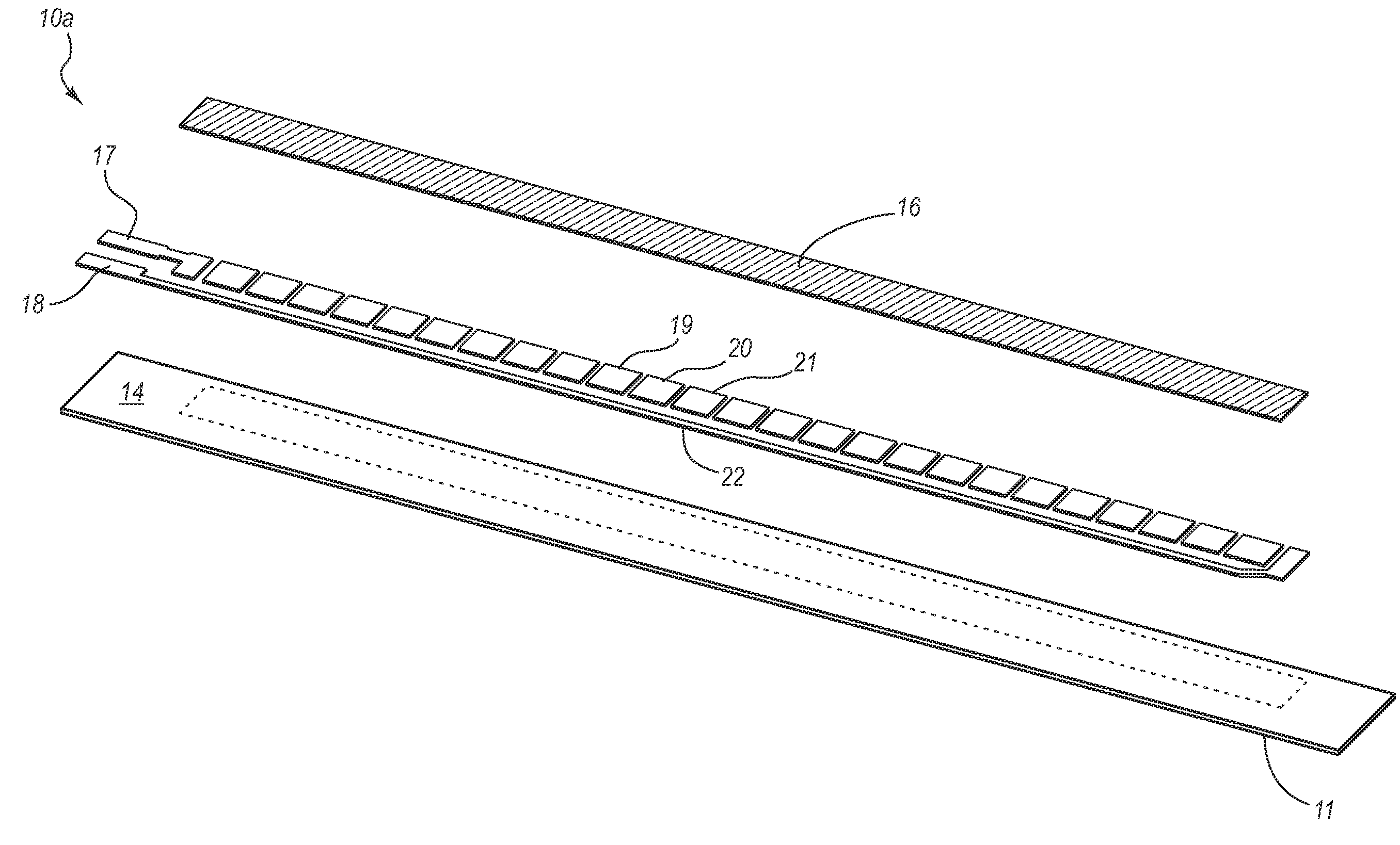
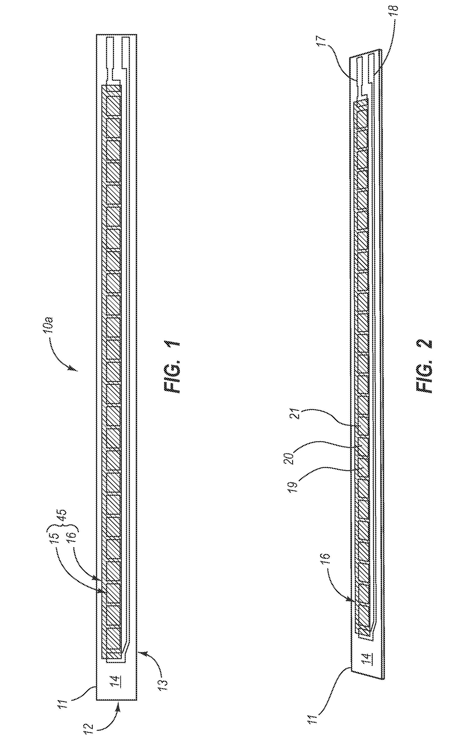
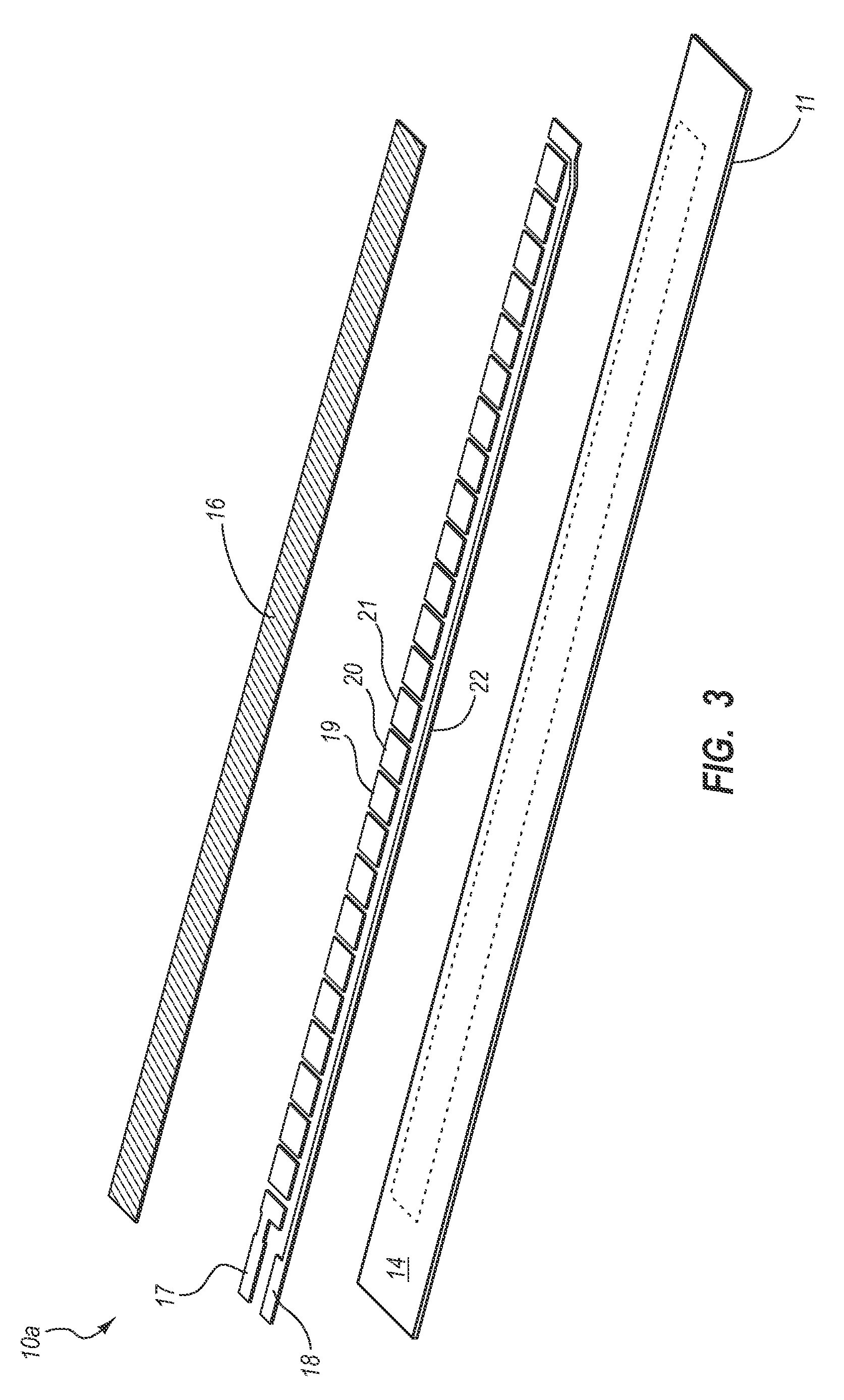
[0026]One or more implementations of the present invention relates to systems, methods, and apparatus for measuring the direction and amount of deflection of an object. In particular, implementations of the present invention comprise a bi-directional bend resistor capable of producing a consistent and predictable variable electrical output upon deflection or bending between configurations occurring in opposite directions from a static configuration. In at least one implementation, a bi-directional bend resistor include a layer of electrically conductive or resistive material, which both increases and decreases its resistance depending upon the direction of deflection from a nominal (static) position.

[0027]For example, one or more implementations of the present invention can include a bi-directional bend resistor that can include a substrate having a top surface with a variable resistance stack thereon. The substrate can be bendable in a first direction (away from the top surface of ...


PUM


Abstract

A system and method for a bi-directional bend resistor are disclosed. The bidirectional deflectable resistor has a variable resistance stack on a top surface of a substrate having a resistance that changes predictably when an electrical signal is applied thereto. The change of resistance of the variable resistance stack reflects an amount of deflection of the bi-directional bend resistor. The variable resistance stack allows for the measurement of deflection of the bi-directional bend resistor in all directions.

Description

CROSS-REFERENCE TO RELATED APPLICATIONS[0001]The present invention claims the benefit of priority to U.S. Provisional Application No. 61 / 085,052, filed Jul. 31, 2008, entitled “Bi-Directional Bend Resistor,” the entire content of which is incorporated by reference herein.BACKGROUND OF THE INVENTION[0002]1. The Field of the Invention[0003]This invention relates to electrical components and more particularly to deflectable resistors which vary in electrical resistance.[0004]2. Background and Relevant Art[0005]Conductive ink potentiometers are standard elements of electrical and electronic circuits. They are widely in use today for a variety of purposes including the measurement of mechanical movement. For example U.S. Pat. No. 5,157,372 (Langford), U.S. Pat. No. 5,583,476 (Langford), and U.S. Pat. No. 5,086,785 (Gentile et al.), the entire contents of which are incorporated by reference herein, disclose sensors for detecting the angular displacement of an object.[0006]The use of elect...

Claims


Application Information

Patent Timeline
Patent Type & Authority Applications(United States)
IPC IPC(8): H01C3/06
CPCH01C10/106
Inventor IOVINE, JOHN
Owner IMAGES SCI INSTR
Why Eureka
Try Eureka