
Method of correcting alignment error of array inkjet head

a technology of array inkjet printhead and alignment error, which is applied in the direction of printing, other printing apparatus, etc., can solve the problems of difficult to arrange the head chips without an offset in the sub-scanning direction, the difficulty of achieving alignment accuracy, and the difficulty of a single head chip to be embodied in a single head chip

Inactive Publication Date: 2010-07-08
S PRINTING SOLUTION CO LTD
View PDF4 Cites 13 Cited by
  • Summary
  • Abstract
  • Description
  • Claims
  • Application Information

AI Technical Summary

Benefits of technology

[0020]The controller can select one of the test lines of a first other head chip which most closely matches a reference line of the reference head chip in the sub-scanning direction, can determine the amount of offset of the first other head chip relative to the reference head chip by comparing t

Problems solved by technology

However, the nozzle unit of the array inkjet printhead is difficult to be embodied in a single head chip.
However, it is very difficult to arrange the head chips without an offset in the sub-scanning direction.
Accordingly, the manufacturing costs rise to obtain accuracy in the alignment in the sub-scanning direction in a manufacturing process.

Method used


Image

  • Method of correcting alignment error of array inkjet head
  • Method of correcting alignment error of array inkjet head
  • Method of correcting alignment error of array inkjet head

Examples


Embodiment Construction

[0029]Reference will now be made in detail to the embodiments of the present general inventive concept, examples of which are illustrated in the accompanying drawings, wherein like reference numerals refer to the like elements throughout. The embodiments are described below in order to explain the present general inventive concept by referring to the figures.

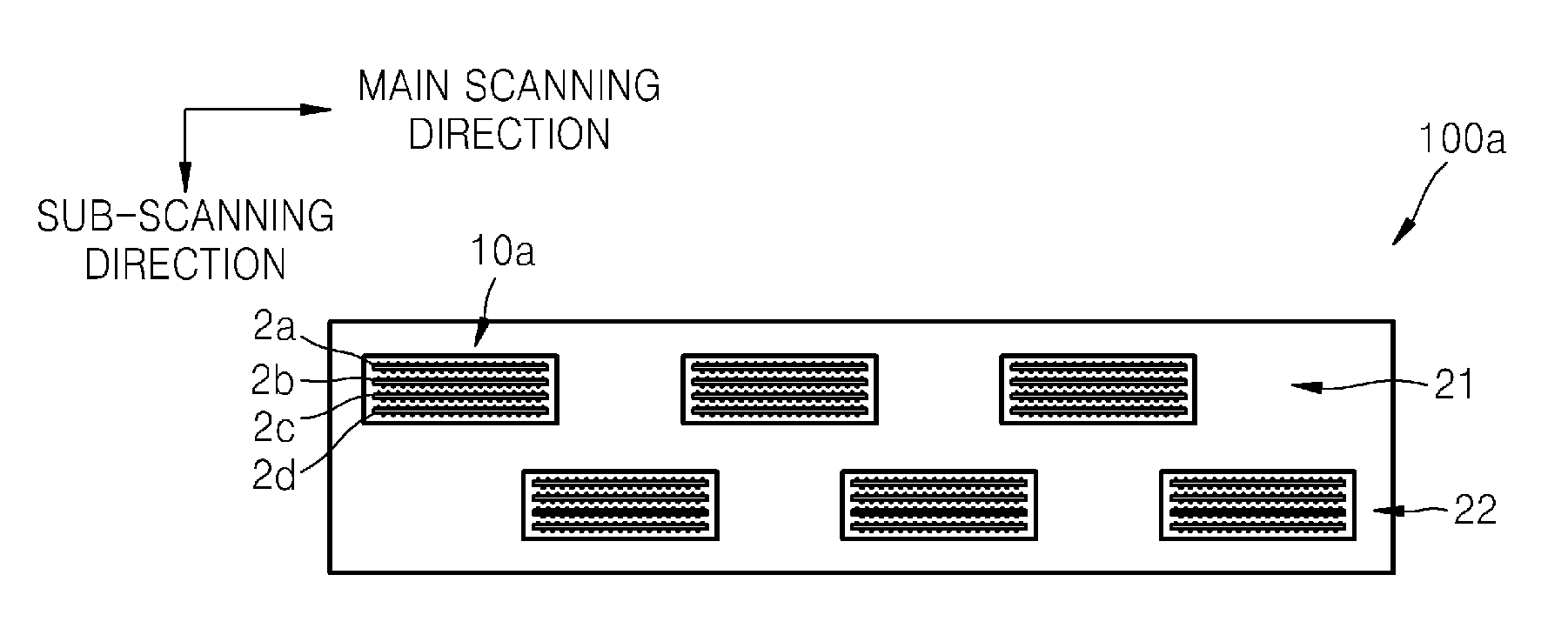
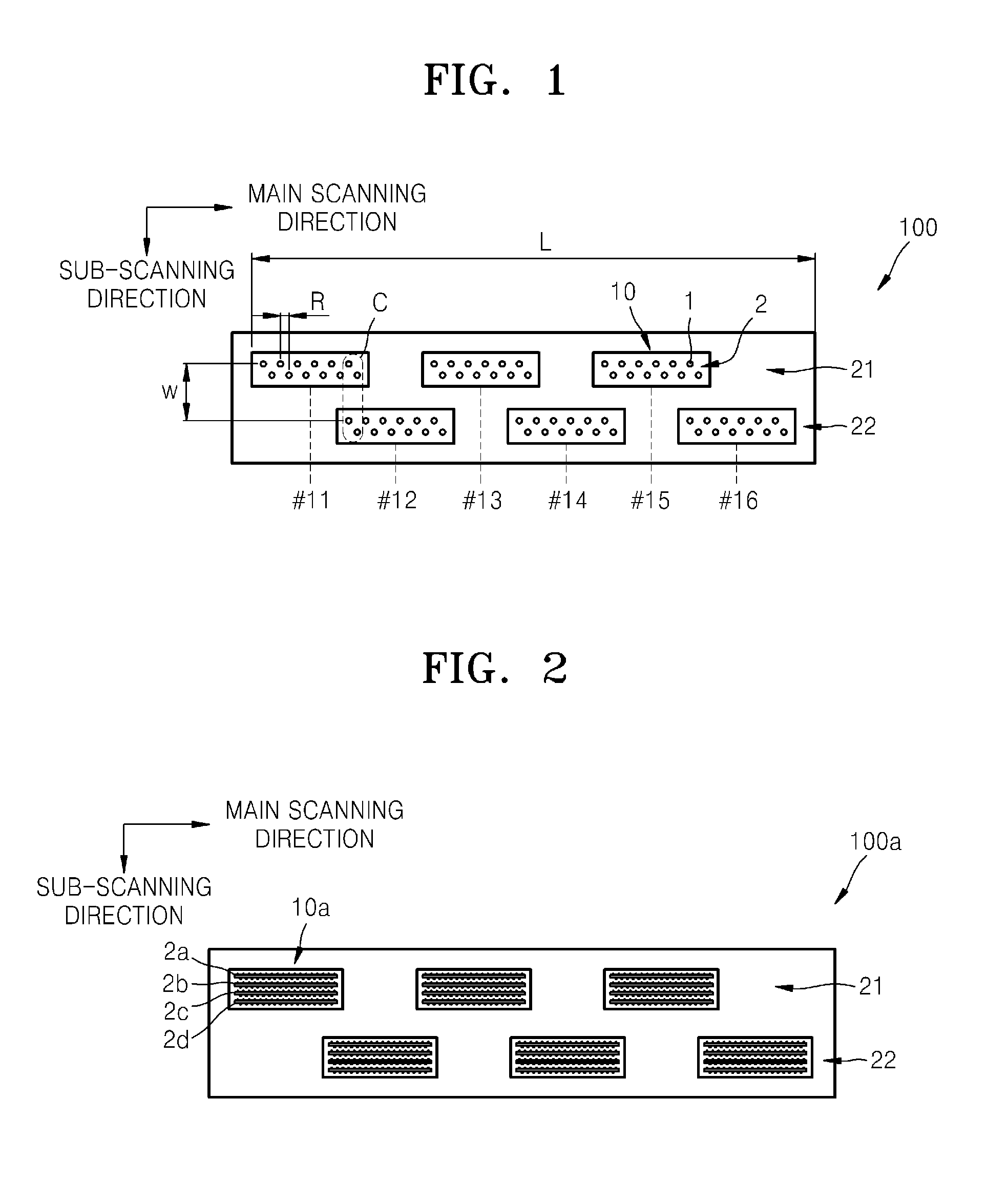
[0030]FIG. 1 is a plan view of an array inkjet printhead 100 using a method of correcting an alignment error according to an embodiment of the present general inventive concept. Referring to FIG. 1, the array inkjet printhead 100 can be embodied by arranging a plurality of head chips 10 in a main scanning direction. The overall length L of the head chips 10 in the main scanning direction can be greater than the width of the paper to be printed.

[0031]The head chip 10 can have a structure capable of ejecting ink supplied from an ink tank (not illustrated) through a nozzle 1 by applying pressure to the ink using a predetermined eje...


PUM


Abstract

A system and method of correcting an alignment error of an array inkjet head having a plurality of head chips to print a main scanning line can include determining a reference head chip, printing a plurality of reference lines in the main scanning direction to be separated from one another at a reference interval in a sub-scanning direction using the reference head chip, and printing a plurality of test lines which can be offset by a multiple m, where m is an integer, of a test interval with respect to the reference interval using other head chips, and determining one of the plurality of test lines that matches any of the plurality of reference lines of each of the head chips, and determining an amount of offset of the determined test line as an amount of offset of each head chip.

Description

CROSS-REFERENCE TO RELATED APPLICATIONS[0001]This application claims the benefit of Korean Patent Application No. 10-2009-0001600, filed on Jan. 8, 2009, in the Korean Intellectual Property Office, the disclosure of which is incorporated herein in its entirety by reference.BACKGROUND[0002]1. Field of the Invention[0003]The present general inventive concept relates to a system and method of correcting an alignment error of an array inkjet printhead having a plurality of head chips, and more particularly to a method of correcting an alignment error in a sub-scanning direction.[0004]2. Description of the Related Art[0005]In general, inkjet image forming apparatuses form an image on paper transferred in a sub-scanning direction by ejecting ink from a shuttle type inkjet printhead that reciprocates in a main scanning direction. The inkjet printhead typically includes at least one inkjet head chip that includes a plurality of nozzles for ejecting ink and an ejection unit providing an ink ...

Claims


Application Information

Patent Timeline
IPC IPC(8): B41J29/38
CPCB41J2/155B41J2/2135B41J2/04505B41J2/14072B41J2/16517B41J2/16544B41J2/16585B41J2/2139B41J11/005B41J29/38
Inventor CHO, SEO-HYUN
Owner S PRINTING SOLUTION CO LTD
Learn More