Image generating method, image generating apparatus and radiation tomographic imaging apparatus, and program therefor

Active Publication Date: 2013-09-19
GENERAL ELECTRIC CO
View PDF1 Cites 6 Cited by
  • Summary
  • Abstract
  • Description
  • Claims
  • Application Information

AI Technical Summary

Benefits of technology

[0028]In a nineteenth aspect, the radiation tomographic imaging apparatus according to any one of the thirteenth through eighteenth aspects is provided, in which the data acquiring unit assigns views for performing the acquisition of actual data to a rotating angle per rotation of each of the radiation source and the detector 1200 more to thereby acquire the fan beam projection data of the plural views.
[0029]In a twentieth aspect, a program is provided. The program allows a computer to function as data converting unit for performing a rearrangement process and an interpolation process on fan beam projection data of a plurality of views acquired by a scan for rotating a radiation source and a detector having a plurality of detecting elements arranged

Problems solved by technology

When, however, the equally-spaced parallel beam projection data acquired by performing the interpolation process in the channel direction are compared with pre-interpolation process dat

Method used


Image

  • Image generating method, image generating apparatus and radiation tomographic imaging apparatus, and program therefor
  • Image generating method, image generating apparatus and radiation tomographic imaging apparatus, and program therefor
  • Image generating method, image generating apparatus and radiation tomographic imaging apparatus, and program therefor

Examples


first embodiment

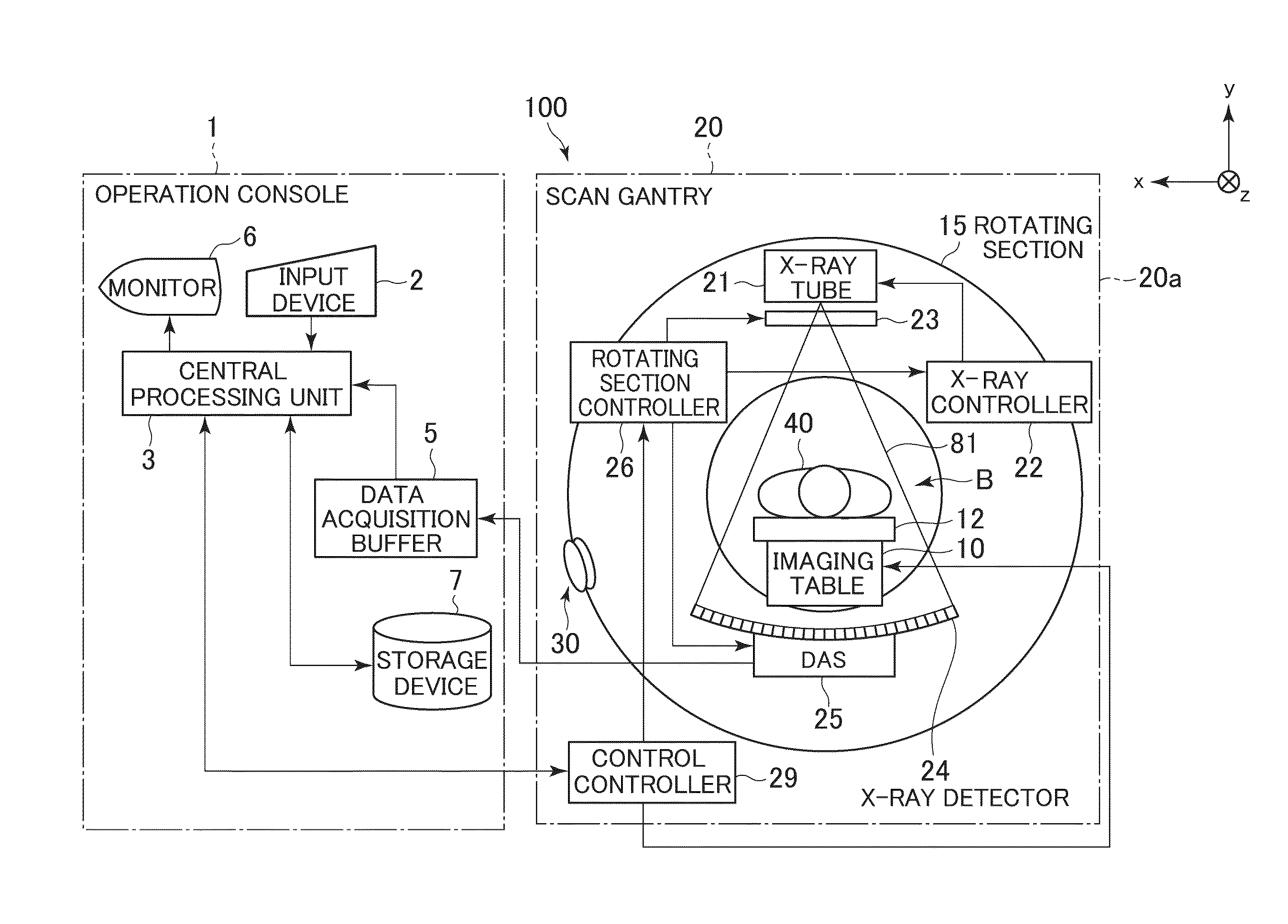
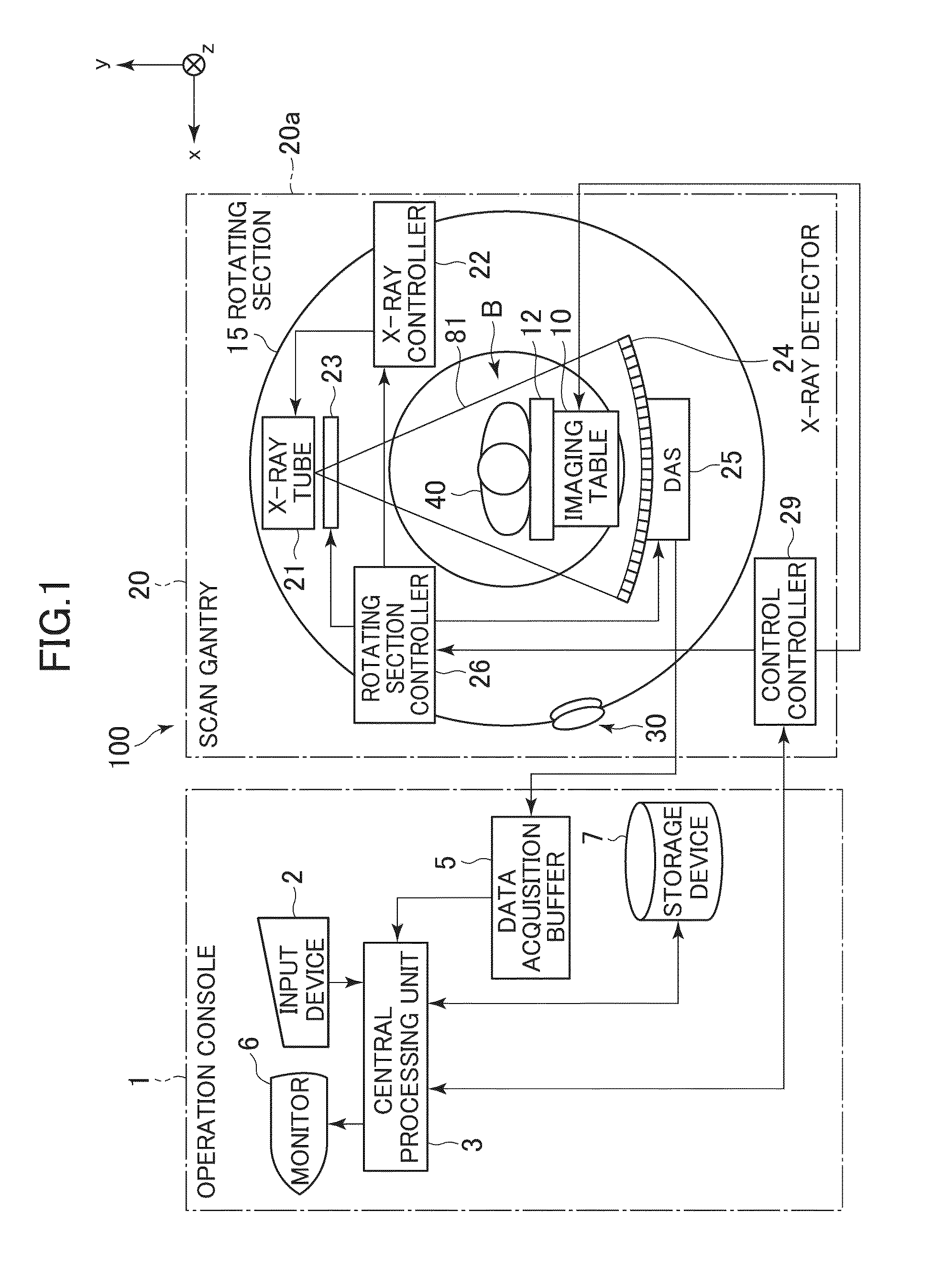
[0044]FIG. 1 is a diagram schematically showing a configuration of an X-ray CT apparatus according to the exemplary embodiment.

[0045]The X-ray CT apparatus 100 is equipped with an operation console 1, a imaging table 10 and a scan gantry 20.

[0046]The operation console 1 is equipped with an input device 2 which accepts an input from an operator, a central processing unit 3 which executes control of respective parts for performing subject's imaging, data processing for generating an image, etc., a data acquisition buffer 5 which acquires or collects data acquired by the scan gantry 20, a monitor 6 which displays each image thereon, and a storage device 7 which stores programs, data, etc. therein.

[0047]The imaging table 10 is equipped with a cradle 12 which conveys a subject 40 to a cavity portion B of the scan gantry 20 with the subject 40 placed thereon. The cradle 12 is elevated and linearly moved horizontally by a motor built in the imaging table 10. Incidentally, in the exemplary ...


PUM


Abstract

An image generating method is provided. The method includes performing a rearrangement process and an interpolation process on fan beam projection data, the fan beam projection data acquired by a scan that includes rotating a radiation source and a detector having a plurality of detecting elements arranged in a channel direction, wherein the interpolation process generates equally-spaced parallel beam projection data in which channel-direction intervals are equal therebetween, and wherein the interpolation process is performed with respect to a plurality of view directions. The method further includes performing a back-projection process on the equally-spaced parallel beam projection data to thereby reconstruct an image, wherein the channel-direction intervals between the equally-spaced parallel beam projection data are smaller than a reference interval obtained by dividing an interval between the detecting elements in the channel direction by a projection enlargement rate.

Description

CROSS REFERENCE TO RELATED APPLICATIONS[0001]This application claims the benefit of Japanese Patent Application No. 2012-57071 filed Mar. 14, 2012, which is hereby incorporated by reference in its entirety.BACKGROUND OF THE INVENTION[0002]The present invention relates to an image generating method, an image generating apparatus and a radiation tomographic imaging apparatus which fan-para convert radiation projection data and perform back projection thereon to thereby reconstruct an image, and a program therefor.[0003]In a third-generation X-ray CT (Computed Tomography) apparatus, X rays of a fan beam are used in the acquisition of projection data. There is a case in which the so-acquired fan beam projection data are converted to parallel beam projection data, followed by being subjected to a back-projection process to reconstruct an image.[0004]This conversion is generally referred to as “fan-para conversion”. An image reconstructing method using the fan-para conversion is called “f...

Claims


Application Information

Patent Timeline
IPC IPC(8): G06T11/00
CPCG06T11/005A61B6/032
Inventor HAGIWARA, AKIRA
Owner GENERAL ELECTRIC CO
Why Eureka
Try Eureka