Multi-beam light source, method for manufacturing the same, light scanning unit using the same, and image forming apparatus using the same

a technology of multi-beam light source and light scanning unit, which is applied in the direction of optical light guides, bundled fibre light guides, instruments, etc., can solve the problems of loss of luminous energy of beams, affecting the alignment accuracy of core portions, and affecting the accuracy of beam alignment, so as to achieve suppressed loss of luminous energy and improve accuracy

Inactive Publication Date: 2009-06-02
RICOH PRINTING SYST
View PDF9 Cites 2 Cited by
  • Summary
  • Abstract
  • Description
  • Claims
  • Application Information

AI Technical Summary

Benefits of technology

[0012]A principal object of the present invention is to provide a multi-beam light source in which core portions are not arrayed in two stages but the intervals of the core portions can be reduced, a method for manufacturing the multi-beam light source, a light scanning unit using the multi-beam light source, and an image forming apparatus using the multi-beam light source.
[0032]Due to the invention configured thus, the core portions can be disposed at smaller intervals relatively to the clad diameter and with higher accuracy. Thus, the loss of luminous energy can be suppressed to be as low as possible.

Problems solved by technology

The alignment accuracy of core portions is an essential problem in light scanning with high accuracy.
When an array of a plurality of optical fibers is used as a light source for a light scanning unit, it is generally a problem that the diameter of a core portion of each optical fiber is significantly smaller than the diameter of a clad portion thereof. FIGS. 13 and 14 show the relationship between an aperture diameter and a beam spot diameter.
There is a problem that the luminous energy of the beam is lost.
However, there is a problem that etching easily leads to a variation in thickness of removal.
There is also a problem that the workability is low when the clad portions whose diameters have been narrowed by etching are fixed to groove portions of a substrate individually by a method such as bonding.
However, in the case where the light guide parts are used as light sources for a light scanning unit, there is a problem that the light sources arrayed in two stages lead to separation when beams emitted from the light sources are incident on a light deflecting unit such as a polygon mirror.
However, due to a complicated configuration, there arises a problem that the optical path length is increased, or the like.
The beam diameters become unstable spatially.
Thus, this method is not practical.

Method used


Image

  • Multi-beam light source, method for manufacturing the same, light scanning unit using the same, and image forming apparatus using the same
  • Multi-beam light source, method for manufacturing the same, light scanning unit using the same, and image forming apparatus using the same
  • Multi-beam light source, method for manufacturing the same, light scanning unit using the same, and image forming apparatus using the same

Examples


Embodiment Construction

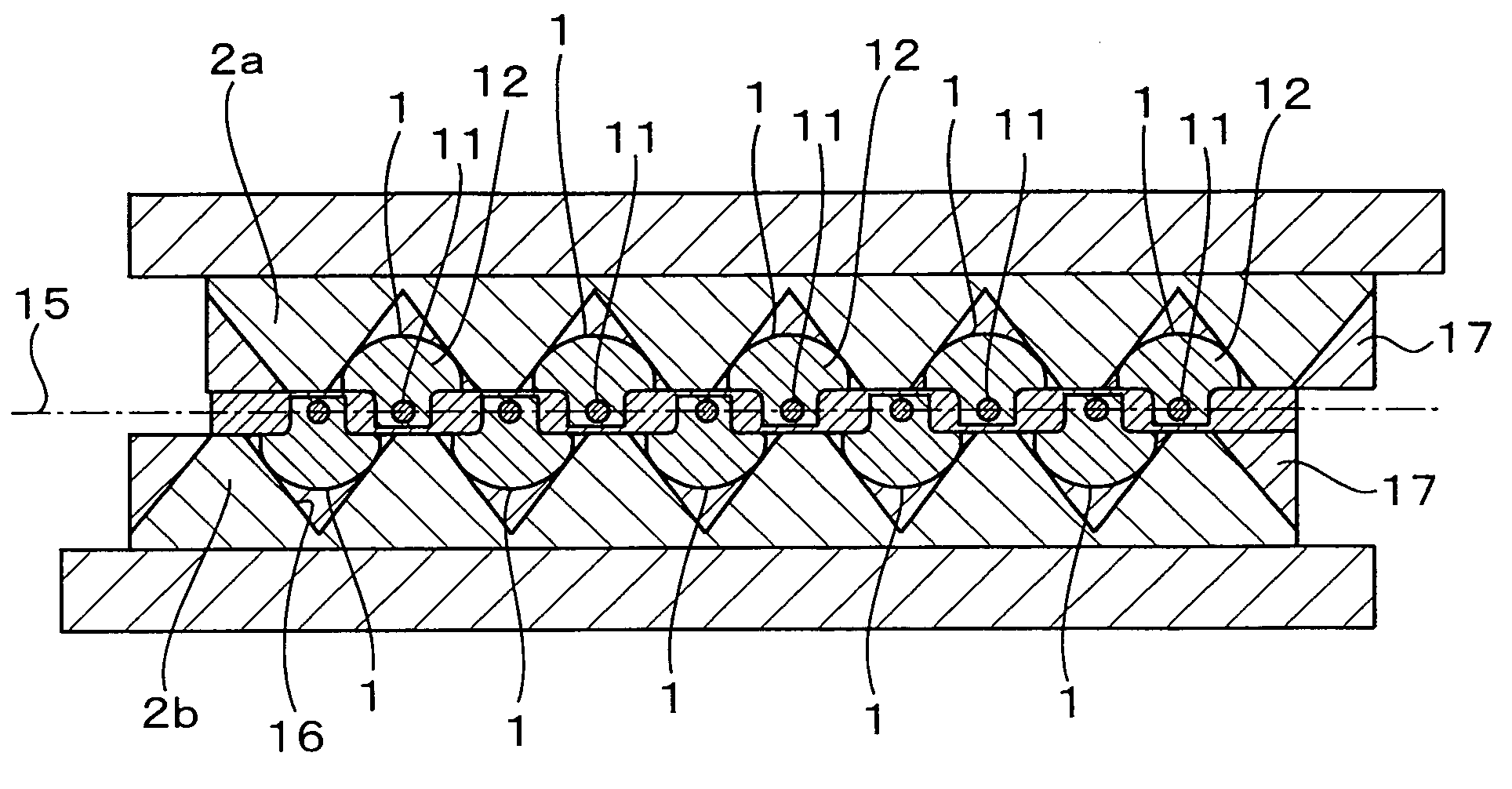
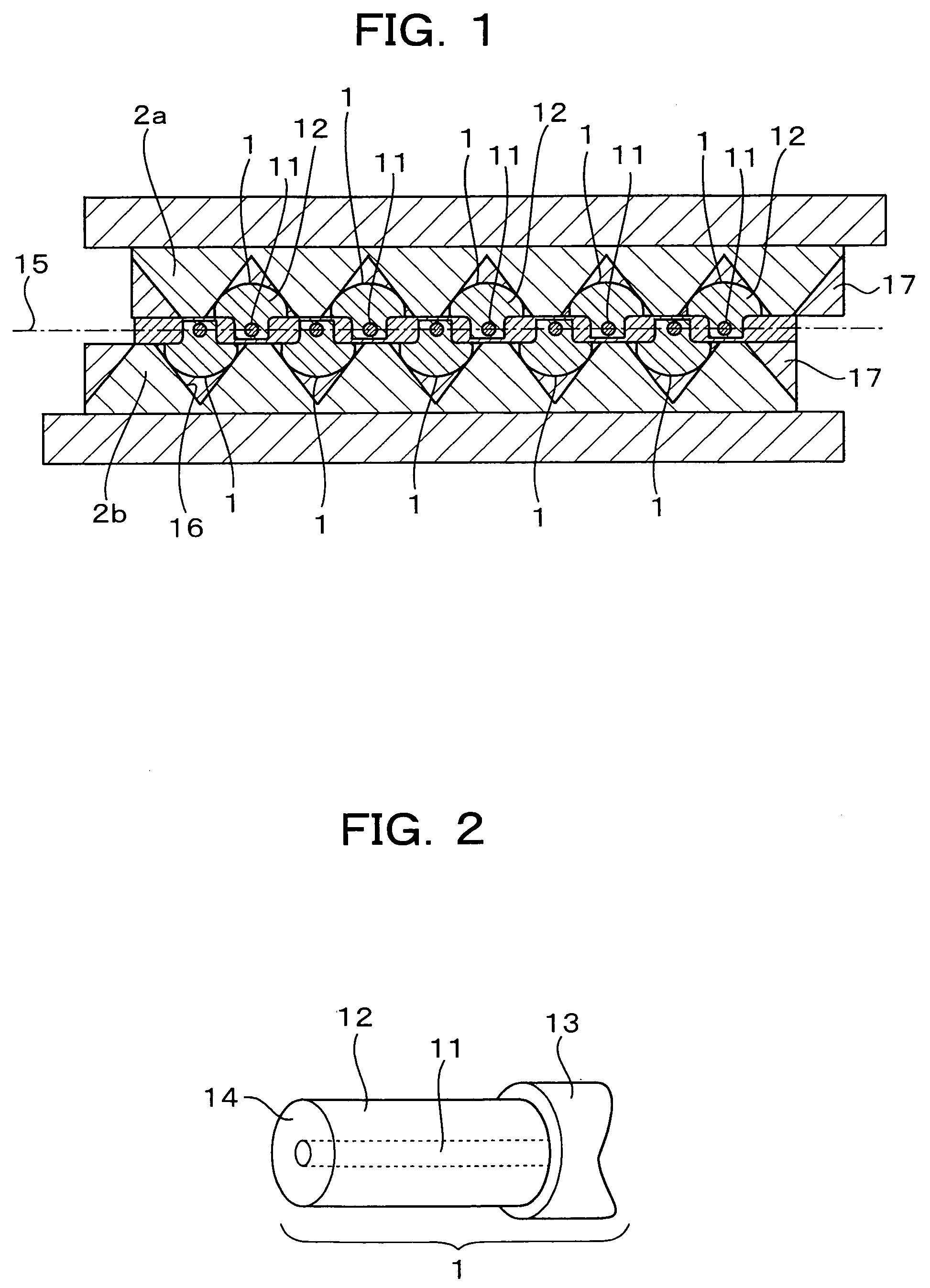
[0047]FIG. 2 is a perspective view showing a fundamental structure of an optical fiber which can be used in this embodiment. In FIG. 2, the reference numeral 1 represents an optical fiber; 11, a core portion; 12, a clad portion; 13, a coating portion; and 14, an end surface of the optical fiber 1. The optical fiber 1 is constituted by the core portion 11 having a comparatively high refractive index, the clad portion 12 surrounding the core portion 11 coaxially, and the coating portion 13 in the periphery of the clad portion 12. The optical fiber 1 also has the end surface 14 perpendicular to the direction in which the core portion 11 and the clad portion 12 extend. Light (laser beam) incident on the other not-shown end surface is emitted from the core portion 11 in the end surface 14. The coating portion 13 is removed in the vicinity of the end surface 14 so that the clad portion 12 is exposed. The exposed clad portion 12 is, for example, about 3-6 mm long. The exposed clad portion ...


PUM


Abstract

The invention is to provide a multi-beam light source where the interval of core portions is reduced and the core portions are arranged on a straight line. The multi-beam light source includes a first substrate where a plurality of optical fibers each having a core portion and a clad portion surrounding the core portion coaxially are fixed at predetermined intervals, and a second substrate where a plurality of similar optical fibers are fixed at predetermined intervals. The first and second substrates are put and bonded on top of each other so that the core portion of each optical fiber on the second substrate is inserted between core portions of adjacent optical fibers on the first substrate, and the core portions of the optical fibers on the first and second substrate are arranged substantially on a straight line.

Description

FIELD OF THE INVENTION[0001]The present invention relates to a multi-beam light source suitable to a light scanning unit or the like using multiple beams, and a method for manufacturing the multi-beam light source.DESCRIPTION OF THE BACKGROUND ART[0002]Techniques using an array of a plurality of optical fibers as a light source for a light scanning unit have been disclosed (see JP-A-2004-258566 and JP-A-2001-66438). The alignment accuracy of core portions is an essential problem in light scanning with high accuracy.[0003]When an array of a plurality of optical fibers is used as a light source for a light scanning unit, it is generally a problem that the diameter of a core portion of each optical fiber is significantly smaller than the diameter of a clad portion thereof. FIGS. 13 and 14 show the relationship between an aperture diameter and a beam spot diameter.[0004]In FIGS. 13 and 14, the reference numeral 11 represents a core portion; 12, a clad portion; 91, a light source portion...

Claims


Application Information

Patent Timeline
Patent Type & Authority Patents(United States)
IPC IPC(8): G02B6/00G02B26/08G02B6/04
CPCG02B6/3636G02B6/3676G02B6/3692G02B26/123
Inventor MOCHIZUKI, TAKESHIKUGAI, KENICHI
Owner RICOH PRINTING SYST
Why Eureka
Try Eureka