
Correlation method to adaptively operate in time varying phase and correlator thereof

a correlation method and time-varying technology, applied in the field of correlation methods and correlators, can solve the problems of requiring relatively large snrs, prone to errors in the mentioned technique, and requiring large snrs

Inactive Publication Date: 2007-05-31
SAMSUNG ELECTRONICS CO LTD
View PDF3 Cites 6 Cited by
  • Summary
  • Abstract
  • Description
  • Claims
  • Application Information

AI Technical Summary

Benefits of technology

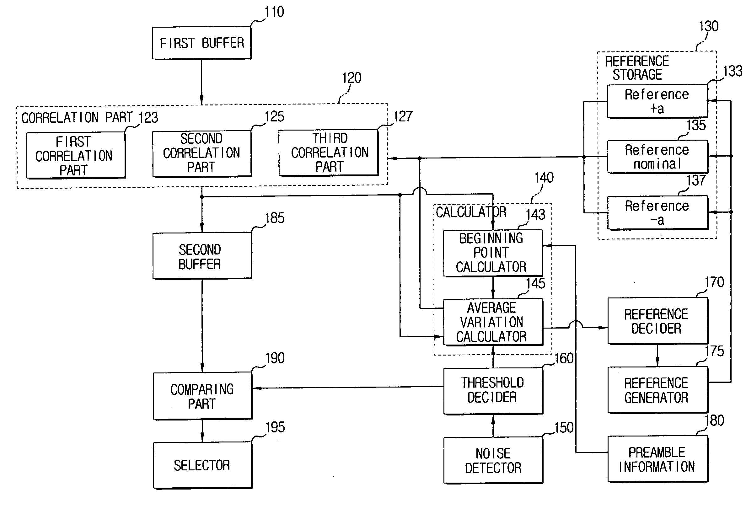
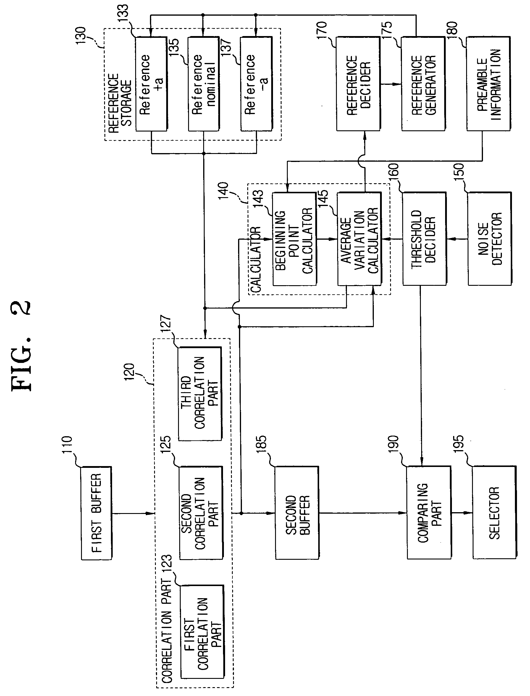
The present invention provides a correlation method and a correlator to demodulate a digital signal in the environment where a variation of signal phase between symbols in one tag and between tags appears. The correlation method involves performing a first correlation based on a reference value and a reference interval, calculating an average variation of the received signal based on the first correlation, deciding a new reference value based on the average variation, performing a second correlation based on the new reference value and the reference interval, and selecting the maximum value from the results of the second correlation. The correlation method is designed to account for bit variations and can be used in a variety of applications such as communication systems or data storage devices. The correlator includes a correlation part, a calculator, a reference decider, and a selector to perform the correlation method. The technical effects of the invention include improved demodulation of digital signals and improved performance in environments where signal phase variations occur.

Problems solved by technology

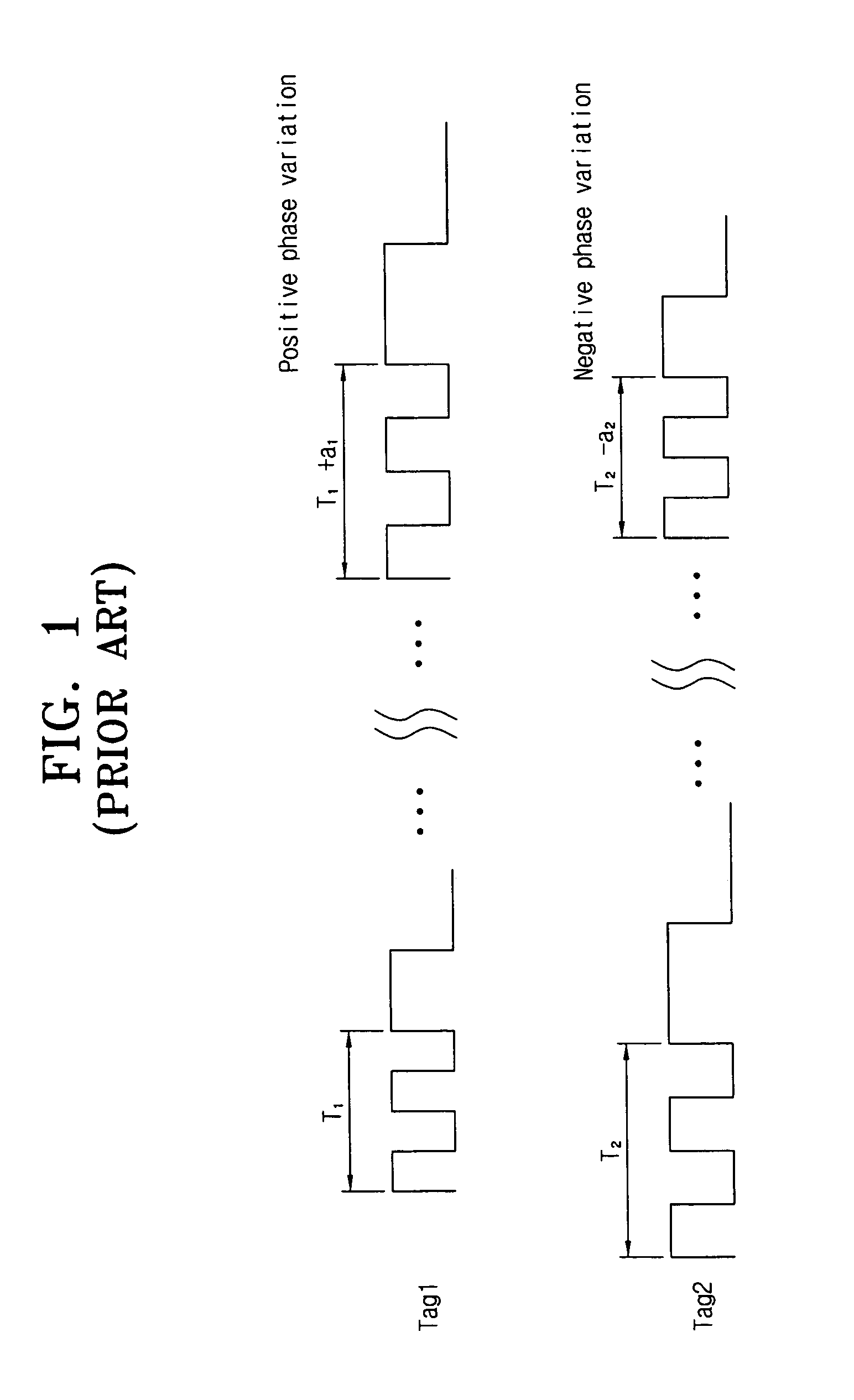
The variation can also be due to an unstable tag clock.
However, the zero-crossing detector requires relatively large SNR which can not be frequently provided in backscatter communications.
If the assumption of invariance in question is violated, the mentioned technique is likely to produce errors.

Method used


Image

  • Correlation method to adaptively operate in time varying phase and correlator thereof
  • Correlation method to adaptively operate in time varying phase and correlator thereof
  • Correlation method to adaptively operate in time varying phase and correlator thereof

Examples


Embodiment Construction

[0036] Hereinafter, an embodiment of the present invention will be described in detail with reference to the accompanying drawing figures.

[0037] In the following description, same drawing reference numerals are used for the same elements even in different drawings. The matters defined in the description such as a detailed construction and elements are nothing but the ones provided to assist in a comprehensive understanding of the invention. Thus, it is apparent that the present invention can be carried out without those defined matters. Also, well-known functions or constructions are not described in detail since they would obscure the invention in unnecessary detail.

[0038] A correlation method and correlator intend to ideally demodulate a digital signal in the environment where a variation of a signal phase between symbols in one tag and / or between tags appears is provided.

[0039] A signal has a preamble section and a data section. In an exemplary implementation of the present in...


PUM


Abstract

Disclosed is a correlation method to adaptively operate in a time varying phase and a correlator thereof. A correlation method according to the present invention includes performing the first correlation according to a certain reference value and a certain reference interval for correlation of a received signal; calculating an average variation of the received signal through the result of performing the first correlation; deciding a new reference value for the second correlation through the average variation; performing the second correlation according to the new reference value and the reference interval; and selecting the maximum value among the result of performing the second correlation. Accordingly, plural references are decided considering variation of a response signal between tags and also separate plural references are decided considering bit variation of a response signal in the same tag, so that a digital signal can be ideally demodulated in the environment where signal phase variation occurs.

Description

CROSS-REFERENCE TO RELATED APPLICATIONS [0001] This application claims benefit under 35 U.S.C. §119(a) of Korean Patent Application No. 2005-115570, filed Nov. 30, 2005 in the Korean Intellectual Property Office, the entire contents of which are incorporated herein by reference. BACKGROUND OF THE INVENTION [0002] 1. Field of the invention [0003] The present invention relates to a correlation method and a correlator. More particularly, the present invention relates to a correlation method to adaptively operate in a time varying phase and a correlator thereof. [0004] 2. Description of the Related Art [0005] A correlator is an electronic device to separate a weak information signal from noise by estimating a correlation function. Correlators such as a magnetic correlator and a cross correlator are known in the art. [0006] Bit variations frequently occur in tags, specifically in low-cost tags that are essential to implement a ubiquitous computing technology. These variations can occur i...

Claims


Application Information

Patent Timeline
Patent Type & Authority Applications(United States)
IPC IPC(8): G06F17/15
CPCH04B1/707H04B1/7093H04B1/7095G06K17/00
Inventor MOUTCHKAEV, ARTEMKANG, WOO-SHIKKOO, SI-GYOUNGKOO, JI-HUN
Owner SAMSUNG ELECTRONICS CO LTD
Learn More