Pulsimeter, control method for pulsimeter, wristwatch information device, control program, and recording medium

a technology of pulsimeter and control method, which is applied in the field of pulsimeter, control method of pulsimeter, control program and recording medium, can solve the problem of preventing the accurate calculation of pulsimeter pulse rate, and achieve the effect of accurate calculation

Inactive Publication Date: 2006-12-05
SEIKO EPSON CORP
View PDF4 Cites 25 Cited by
  • Summary
  • Abstract
  • Description
  • Claims
  • Application Information

AI Technical Summary

Benefits of technology

[0007]Accordingly, an object of the present invention is to provide a pulsimeter that allows pulse rates to be accurately calculated even if body motion components overlap pulse wave components.
[0008]A second object of the present invention is to provide a control method for a pulsimeter, a control program for controlling a pulsimeter, and a recording medium having a control program to allow pulse rates to be accurately calculated even if body motion components overlap pulse wave components.SUMMARY OF THE INVENTION

Problems solved by technology

Since this distorts the pulse wave signal, it prevents the accurate calculation of a pulse rate.

Method used


Image

  • Pulsimeter, control method for pulsimeter, wristwatch information device, control program, and recording medium
  • Pulsimeter, control method for pulsimeter, wristwatch information device, control program, and recording medium
  • Pulsimeter, control method for pulsimeter, wristwatch information device, control program, and recording medium

Examples


first embodiment

[0056][1] First Embodiment

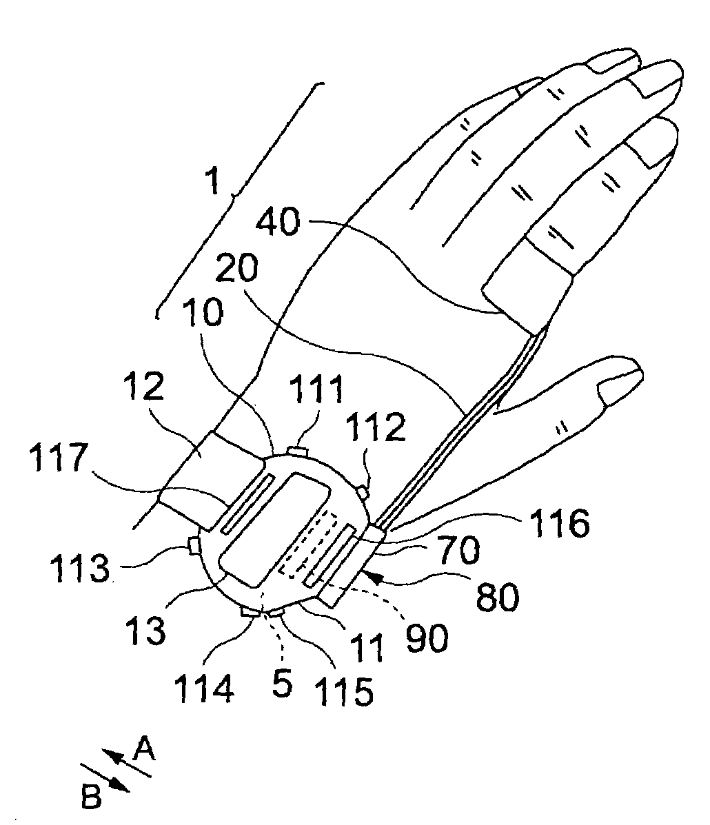
[0057]With reference to FIG. 1, wristwatch information device 1 is primarily constructed of a main body unit 10 preferably having a wristwatch shape, a cable 20 connected to main body unit 10, and a pulse wave sensor 30 provided at the distal end of the cable 20.

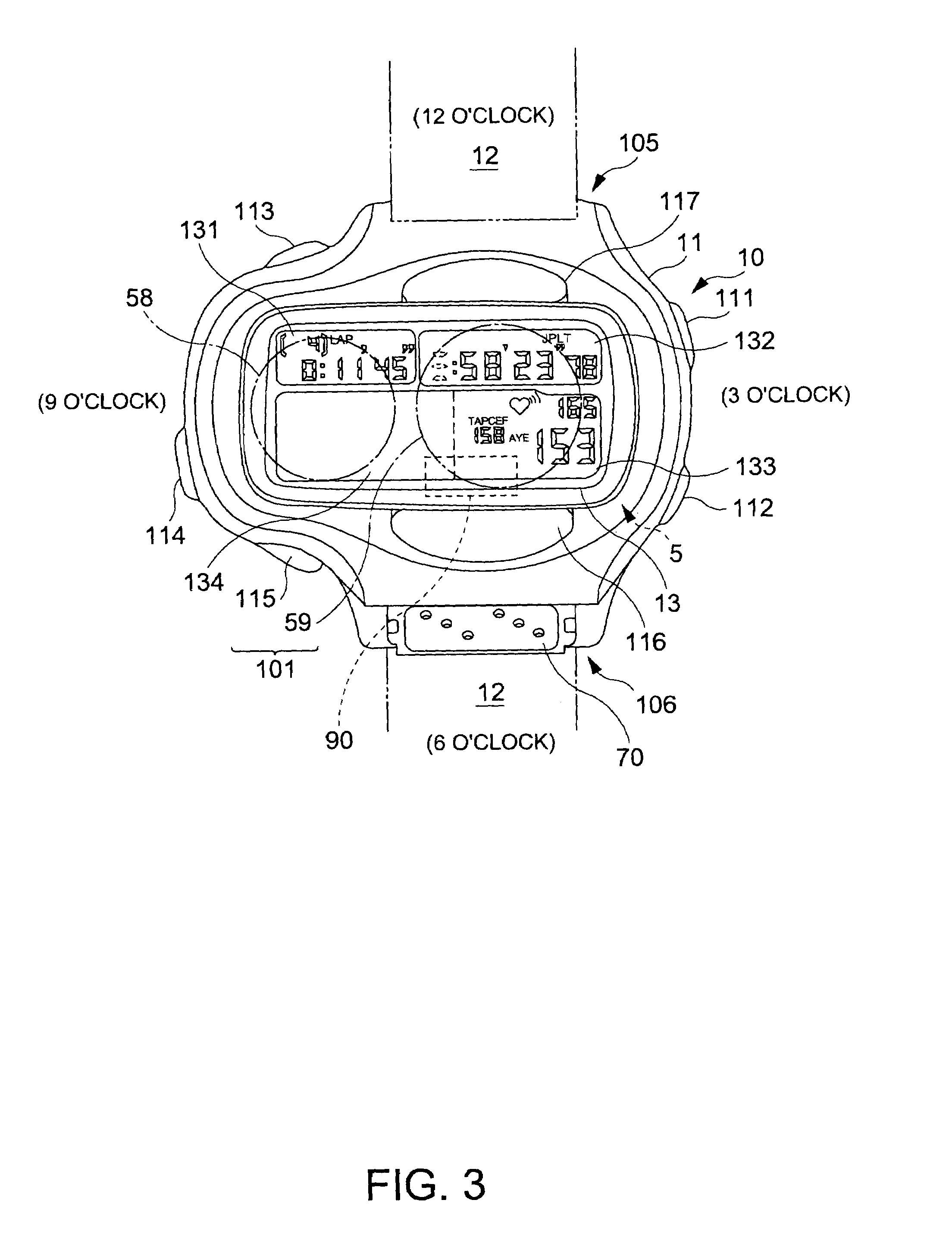
[0058]A connector piece 80 is formed on one end of the cable 20. The connector piece 80 is detachably installed onto a connector 70 preferably provided on the side of main unit 10 adjacent the 6 o'clock position.

[0059]Main unit 10 is provided with a wristband 12 for winding around an arm (or wrist). Preferably wristband 12 winds around from a first fixed location at the 12 o'clock position of a wristwatch to a second fixed location at the 6 o'clock position. Main unit 10 is detachably mounted on the arm by means of this wristband 12.

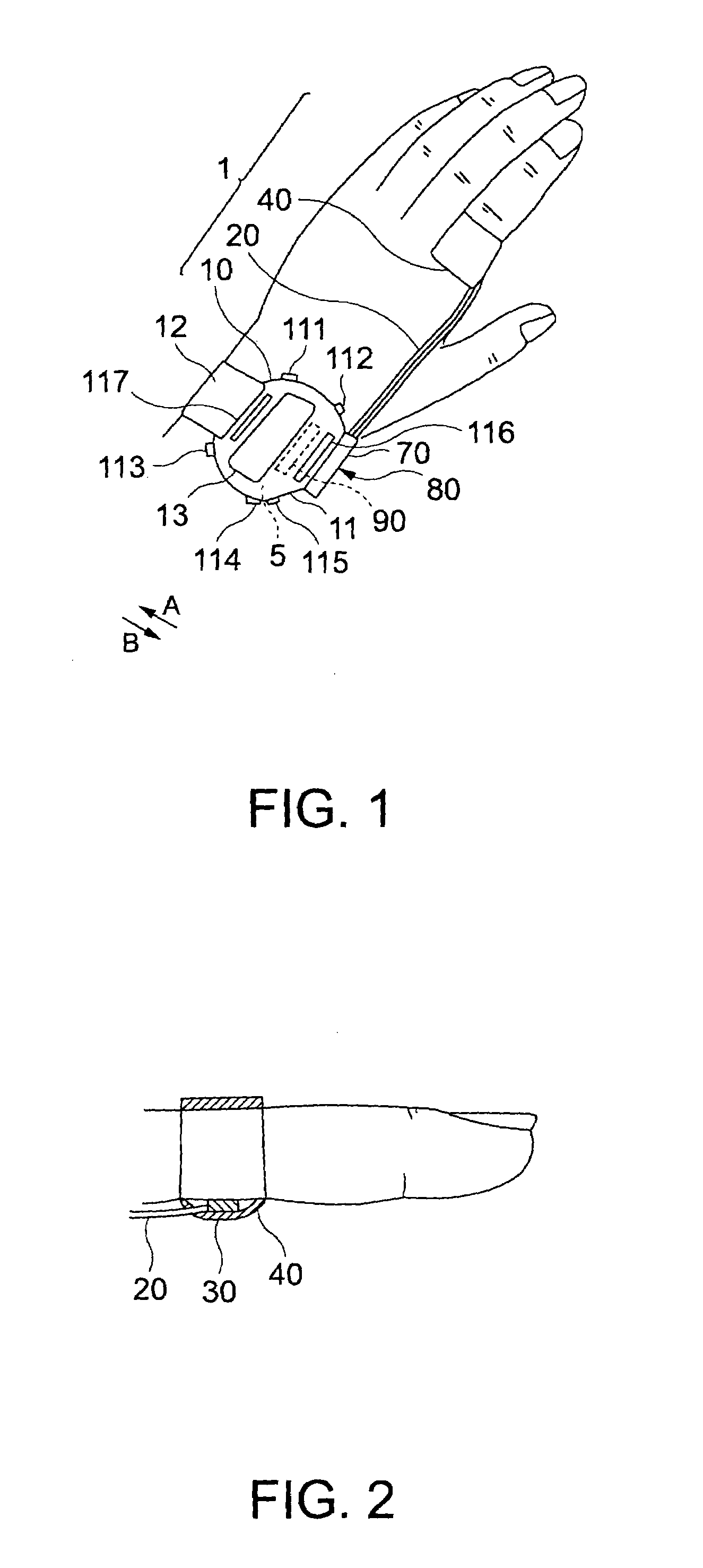
[0060]With reference to FIG. 2, pulse wave sensor 30 is preferably positioned between the base and knuckle joint of a forefinger. Pulse wave sensor 30 is shielded from l...

second embodiment

[0162][2] Second Embodiment

[0163]In the first embodiment, when the frequency component derived from a observed pulse wave and the frequency component derived from a body motion wave share a proximate dominant frequency, the higher harmonic spectrum peak having the largest variation in phase angle is identified as the target spectrum component from which to extract the frequency component of the pure pulse wave. In this second embodiment, a phase angle difference between the phase angles of the higher harmonic spectrum peaks of an observed pulse wave signal and the phase angles of the higher harmonic spectrum peaks of a body motion signal corresponding to the higher harmonics of the observed pulse wave signal is determined. Then, a higher harmonic spectrum peak exhibiting the largest variation per unit time in the phase angle difference is identified as the target spectrum component, i.e. as the frequency component containing pure pulse wave information.

[0164]The second embodiment di...


PUM


Abstract

A frequency analyzer carries out a frequency analysis on a pulse wave signal output from a pulse wave detector. A candidate extractor extracts candidate spectrum peaks from a frequency analysis result of the frequency analyzer. A phase variation calculator calculates variations in phase angle of each of the extracted candidate spectrum peaks, and a spectrum peak selector selects a target spectrum peak from among the extracted candidate spectrum peaks based on their respective variations in phase angle. A pulse rate is calculated using the target spectrum peak.

Description

BACKGROUND OF THE INVENTION[0001]1. Field of the Invention[0002]The present invention relates to a pulsimeter, a control method for a pulsimeter, a control program and a recording medium, and more particularly, it relates to a pulsimeter attached to a part of a human body to measure a pulse rate while walking or running, a control method for a pulsimeter, a control program and a recording medium.[0003]2. Description of the Related Art[0004]Hitherto, there has been known a sphygmograph attached to a part of a human body to measure pulses while walking or running.[0005]For example, Japanese patent No. 2816944 discloses such a wrist pulsimeter. This pulsimeter attempts to remove body motion harmonic components from a pulse wave signal prior to determining the pulse rate from the pulse wave signal. That is, the pulsimeter is constructed to conduct frequency analysis on a body motion signal to identify body motion harmonics, and then to remove all higher body motion harmonic components f...

Claims


Application Information

Patent Timeline
Patent Type & Authority Patents(United States)
IPC IPC(8): A61B5/00A61B5/0245A61B5/024A61B5/11
CPCA61B5/02438A61B5/681
Inventor KOSUDA, TSUKASA
Owner SEIKO EPSON CORP
Why Eureka
Try Eureka