Thermoacoustic device

a technology of thermoacoustic devices and carbon nanotube films, applied in the direction of transducer details, mechanical vibration separation, electrical transducers, etc., can solve the problems of large area, small thickness of carbon nanotube films used in thermoacoustic devices, and sound wave generation

Active Publication Date: 2010-07-08
BEIJING FUNATE INNOVATION TECH
View PDF66 Cites 20 Cited by
  • Summary
  • Abstract
  • Description
  • Claims
  • Application Information

AI Technical Summary

Problems solved by technology

However, the structure of the electric-powered loudspeaker 300 is dependent on magnetic fields and often weighty magnets.
The heating of the medium causes thermal expansion and produces pressure waves in the surrounding medium, resulting in sound wave generation.
The heat capacity per unit area of the platinum strip with the thickness of 7×10⁻⁵ cm is 2×10⁻⁴ J / cm2*K. However, the thermophone adopting the platinum strip, listened to the open air, sounds extremely weak because the heat capacity per unit area of the platinum strip is too high.
The carbon nanotube film used in the thermoacoustic device has a large specific surface area, and extremely small heat capacity per unit area that make the sound wave generator emit sound audible to humans.
However, the carbon nanotube film used in the thermoacoustic device having a small thickness and a large area is easily damaged by the external forces applied thereon.

Method used


Image

  • Thermoacoustic device
  • Thermoacoustic device
  • Thermoacoustic device

Examples


Embodiment Construction

[0055]The disclosure is illustrated by way of example and not by way of limitation in the figures of the accompanying drawings in which like references indicate similar elements. It should be noted that references to “an” or “one” embodiment in this disclosure are not necessarily to the same embodiment, and such references mean at least one.

[0056]Reference will now be made to the drawings to describe, in detail, embodiments of a thermoacoustic device and a speaker using the same.

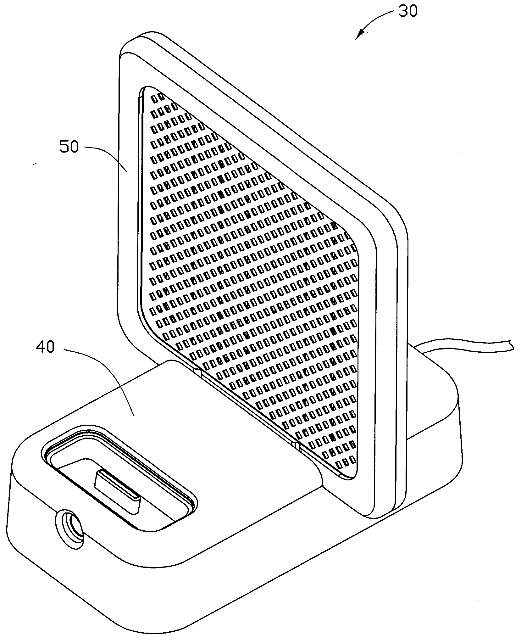
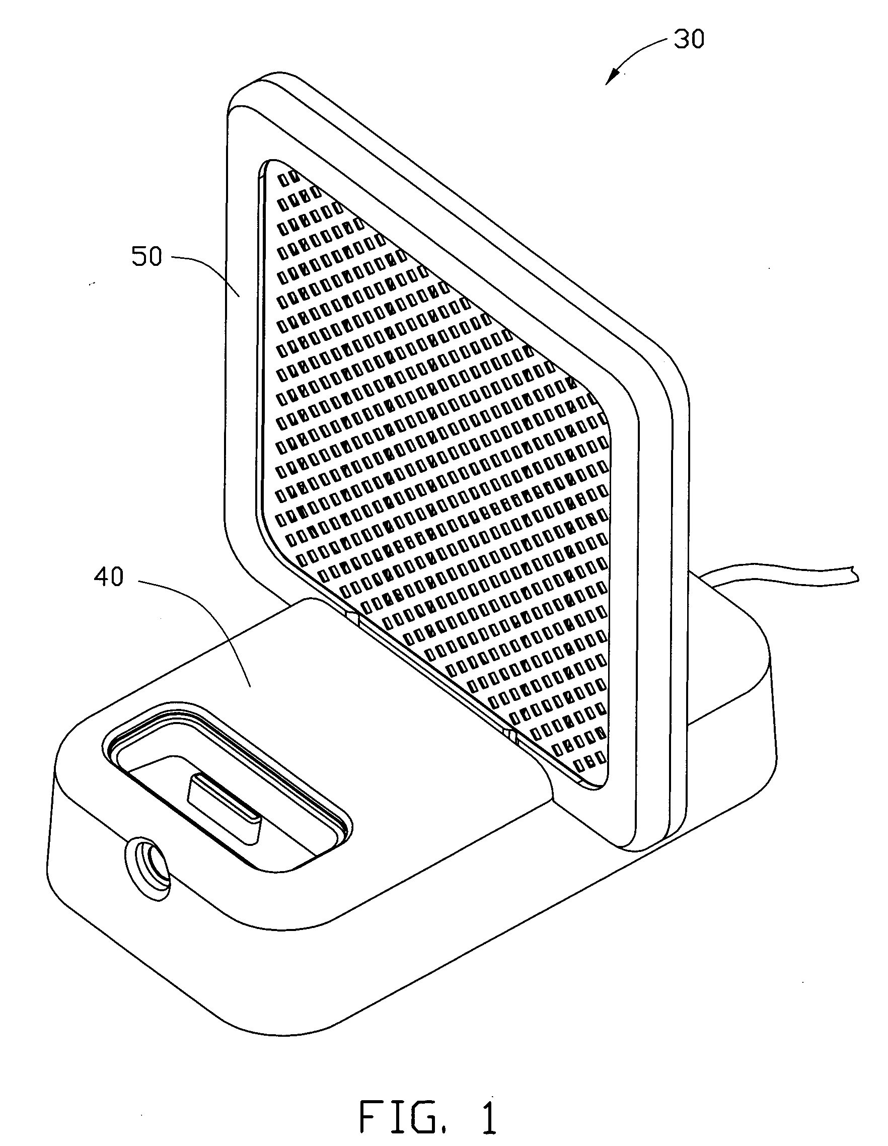
[0057]Referring to the embodiment shown in FIG. 1, a speaker 30 of one embodiment includes a base 40, and a thermoacoustic device 50 detachably installed on the base 40.

Base

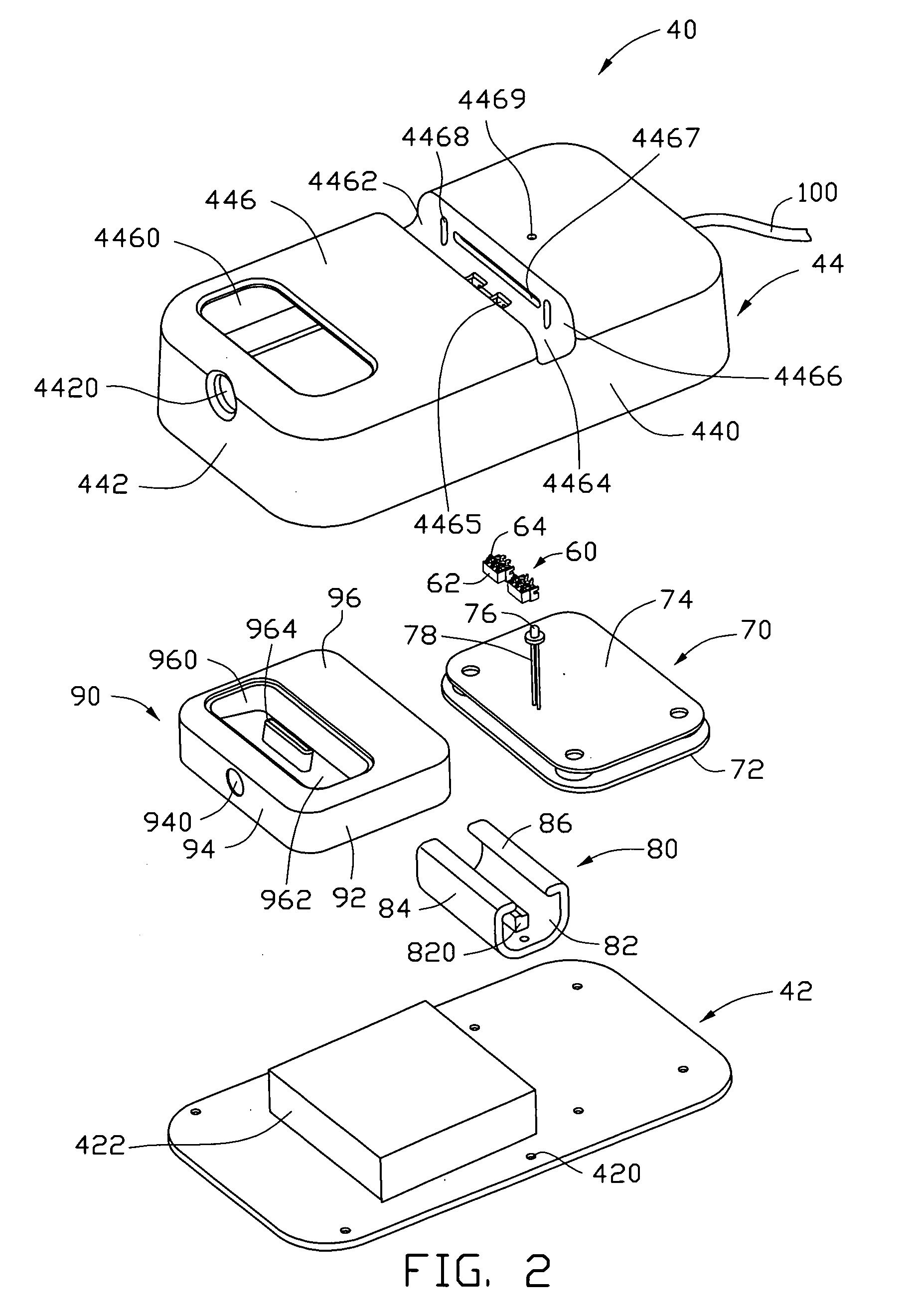
[0058]Referring to the embodiment shown in FIGS. 2 to 3, an embodiment of the base 40 includes a plate 42, a shell 44 covering the plate 42, a first connector 60, a second connector 90, an amplifier circuit device 70, and a fixing piece 80. The plate 42 and the shell 44 form a receiving room 46. The first connector 60, the amplifier circu...


PUM


Abstract

A thermoacoustic device includes a thermoacoustic module and a frame. The thermoacoustic module includes a sound wave generator, at least one first electrode and at least one second electrode. The sound wave generator includes at least one carbon nanotube structure. The at least one first electrode and the at least one second electrode are electrically connected to the sound wave generator. The frame secures the thermoacoustic module.

Description

RELATED APPLICATIONS[0001]This application claims all benefits accruing under 35 U.S.C. §119 from China Patent Application No. 200810191736.6, filed on Dec. 30, 2008; China Patent Application No. 200910000259.5, filed on Jan. 15, 2009 in the China Intellectual Property Office; China Patent Application No. 200810191738.5, filed on Dec. 30, 2008 in the China Intellectual Property Office; China Patent Application No. 200810191735.1, filed on Dec. 30, 2008 in the China Intellectual Property Office; China Patent Application No. 200810191734.7, filed on Dec. 30, 2008 in the China Intellectual Property Office; China Patent Application No. 200810191730.9, filed on Dec. 30, 2008 in the China Intellectual Property Office; China Patent Application No. 200810191733.2, filed on Dec. 30, 2008 in the China Intellectual Property Office; China Patent Application No. 200910169652.7, filed on Aug. 28, 2009 in the China Intellectual Property Office; and China Patent Application No. 200910170294.1, file...

Claims


Application Information

Patent Timeline
Patent Type & Authority Applications(United States)
IPC IPC(8): B06B1/02
CPCH04R23/002H04R2205/021H04R2201/028
Inventor QIAN, LIWANG, YU-QUANFENG, CHENLIU, LIANG
Owner BEIJING FUNATE INNOVATION TECH
Why Eureka
Try Eureka