Clamping device for rotary index device for machine tool

Active Publication Date: 2010-07-15
TSUDAKOMA KOGYO KK
View PDF5 Cites 29 Cited by
  • Summary
  • Abstract
  • Description
  • Claims
  • Application Information

AI Technical Summary

Benefits of technology

[0010]According to the invention of Claim 1, in the rotary index device (1) for the machine tool, in which the index position of the member that is rotationally driven (4), such as a rotary table, is maintained by normally clamping the clamp disc (11) by the clamping means (6) and in which, when an indexing operation is performed, unclamping means (13) causes the clamping means (6) to be set in an unclamped state to cause the member that is rotationally driven (4) to be capable of rotating, the clamping means (6) includes a fixing portion (7), a resiliently deformable supporting portion (8), and urging means (10). The fixing portion (7) is fixed to the housing (3) of the rotary index device (1) for the machine tool. One end of the supporting portion (8) is secured to the fixing portion (7), and a pressing portion (9) having a face that opposes the clamp disc (11) is secured to the other end of the supporting portion (8). The urging means (10) normally urges the pressing portion (9) towards the clamp disc (11) to realize the state in the clamp disc (11) is pressed by the pressing portion (9). That is, the supporting portion (8), including the pressing portion (9) of the clamping means (6), is secured to the housing (3) through the fixing portion (7), and the pressing portion (9) is displaced in an urging direction by resiliently deforming the supporting portion (8). Therefore, compared to the system of the related art in which a clamp disc is clamped by a piston, a structure that guides the piston or a structure that causes the piston to be incapable of rotating in the rotation direction of the rotary shaft is no longer required; and the structure of the clamping means can be simplified. In addition, in the present invention, since the pressing portion (9) that presses the clamp disc (11) is displ

Problems solved by technology

Accordingly, in the type in which the clamp disc is clamped by displacing the piston with respect to the housing in the axial direction of the rotary shaft, the piston needs to have a structure that stops its rotation, thereby complicating the internal structure of a rotary table device and increasing manufacturing costs.
However, in these structures, friction is generated between the piston and a sliding-guidi

Method used


Image

  • Clamping device for rotary index device for machine tool
  • Clamping device for rotary index device for machine tool
  • Clamping device for rotary index device for machine tool

Examples


Embodiment Construction

[0055]The present invention is applied to a rotary index device for a machine tool, used for indexing an angle of a workpiece.

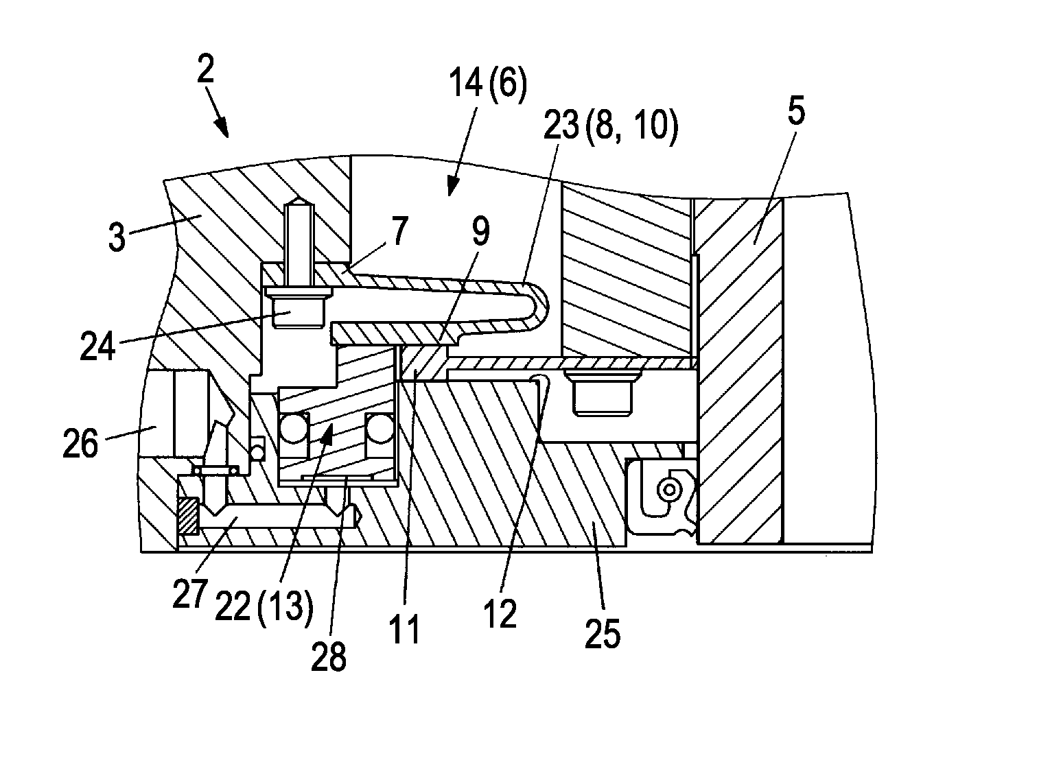
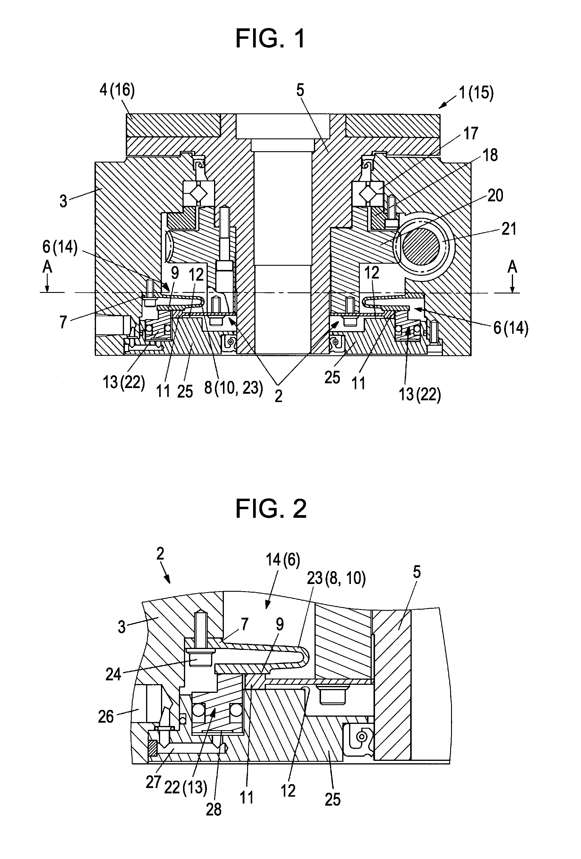
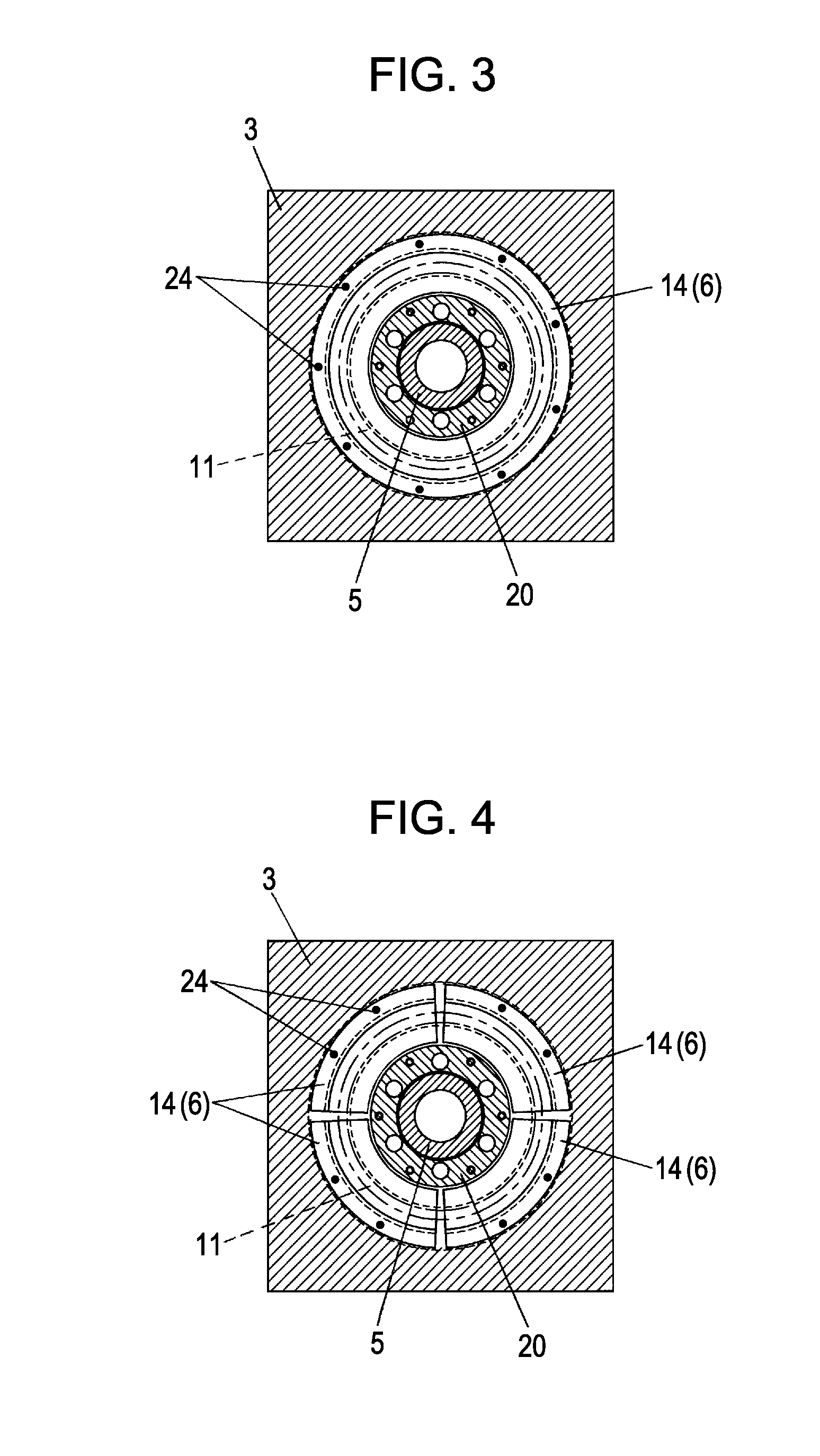
[0056]FIG. 1 shows an embodiment of a rotary table device 15 serving as a rotary index device 1 for a machine tool to which the present invention is applied. The rotary table device 15 is a device in which a circular table 16, which is a member that is rotationally driven 4, is rotatably mounted to a housing 3 serving as a base. The rotary table device 15 is also called an index table or a rotary table.

[0057]The rotary table device 15 is described in more detail. The circular table 16 is secured to one end portion of a rotary shaft 5 rotatably provided in the housing 3. The rotary shaft 5 is supported by a bearing 17 secured to the housing 3 by a bearing sleeve 18.

[0058]As driving means of the rotary table 16, the rotary table device 15 includes a worm wheel 20 secured to the rotary shaft 5, a worm gear 21 rotatably supported by the housing 3 and engaging the...


PUM


Abstract

A clamping device for a rotary index device for a machine tool, in particular, a normal clamp type clamping device makes it possible to simplify the structure thereof and to maintain a stabilized positioning performance. In a rotary index device (1) for the machine tool, in which the index position of, for example, a circular table (16) is maintained by normally clamping a clamp disc (11) with clamping means (6) and in which, for example, the circular table (16) is unclamped by unclamping means (13) when an indexing operation is performed, the clamping means (6) includes a fixing portion (7), a resiliently deformable supporting portion (8), and urging means (10). The fixing portion (7) is fixed to a housing (3) of the rotary index device (1) for the machine tool. One end of the supporting portion (8) is secured to the fixing portion (7), and a pressing portion (9) having a face that opposes the clamp disc (11) is secured to the other end of the supporting member (8). The urging means (10) normally urges the supporting portion (8) towards the clamp disc (11) to realize a state in which the clamp disc (11) is pressed by the pressing portion (9).

Description

TECHNICAL FIELD[0001]The present invention relates to a clamping device for a rotary index device, such as a rotary table device, used in a machine tool.BACKGROUND ART[0002]Patent Document 1 discloses a clamping mechanism of a rotary table device. The clamping mechanism clamps a rotary shaft, to which a circular table is secured, by a clamp disc (brake plate) and a piston serving as clamping means. The clamp disc is mounted to the rotary shaft so as to be incapable of rotating relative to the rotary shaft. The piston is normally urged towards the clamp disc by a coil spring (compression spring).[0003]In the disc type clamping device described above, in order to set the clamp disc in a state in which it is clamped by a piston, that is, in order to set the clamp disc in a state in which it is held so as to be incapable of rotating, it is necessary for the piston to be in a state in which it is incapable of rotating with respect to a housing (frame body). That is, it is necessary for t...

Claims


Application Information

Patent Timeline
IPC IPC(8): B23Q16/10B23Q1/26
CPCB23Q16/102B23Q16/105Y10T74/1453Y10T74/14Y10T74/1494B23Q2220/004B23Q1/28B23Q16/02B23Q16/08B23Q16/10
Inventor TATSUDA, YOSHINORI
Owner TSUDAKOMA KOGYO KK
Why Eureka
Try Eureka