Tone synthesis apparatus and method

a tone and apparatus technology, applied in the field of tone synthesizers, can solve the problems of inability to reproduce the reed of an actual wind instrument faithfully, and it is difficult to synthesize tones sufficiently close to the reed of an actual wind instrument, so as to achieve accurate reproduction, and accurate synthesizing of tones.

Inactive Publication Date: 2010-07-15
YAMAHA CORP
View PDF14 Cites 4 Cited by
  • Summary
  • Abstract
  • Description
  • Claims
  • Application Information

AI Technical Summary

Benefits of technology

[0006]Because the displacement of the reed is calculated on the basis of the motion equation of coupled vibration, the present invention can accurately simulate behavior of the reed as compared to the conventional construction where behavior of the reed is calculated on the basis of a motion equation that does not reflect therein. As a result, the present invention can faithfully reproduce tones of an actual wind instrument.
[0008]In a preferred embodiment, the first motion equation and the second motion equation include a spring constant of the lip that changes in accordance with a position in the lip and intensity of pressing force acting on the lip. Such an arrangement can faithfully simulate the characteristic of an actual lip that a spring constant of the lip changes in accordance with the intensity of the pressing force and the position in the lip. As a result, the present invention can accurately synthesize tones of a wind instrument.
[0009]In a preferred embodiment, the first motion equation includes bending rigidity that changes in accordance with a position of the reed. Such an arrangement can faithfully simulate the characteristic of an actual reed that bending rigidity of the reed (product between a second moment of area and a Young's modulus of the reed MR) changes in accordance with the position of the reed. As a result, the present invention can accurately synthesize tones of a wind instrument as compared to the conventional construction where the reed is simulated with a mere elongated plate-shaped vibrating member that does not change in sectional shape.
[0010]In a preferred embodiment, the second arithmetic operation section limits the displacement of the reed to within a predetermined range. Because the displacement of the reed calculated on the basis of the motion equation of coupled vibration is limited to within the predetermined range, it is possible to prevent simulation of a situation where the reed is displaced to outside a displacement range of an actual reed, so that tones of an actual wind instrument can be reproduced accurately. The range within which the displacement of the reed is limited is preferably set to a range from the bottom surface of the lip and a surface of the mouthpiece opposed to the bottom surface.
[0011]In a preferred embodiment, the motion equation of coupled vibration includes at least one of internal resistance of the lip that changes in accordance with a position in the lip and internal resistance of the reed that changes in accordance with a position in the reed. Such an arrangement can simulate a situation where the internal resistance of the lip and internal resistance of the reed change in accordance with the positions, and thus, the present invention can faithfully reproduce tones of an actual wind instrument as compared to the conventional construction where the internal resistance of the lip and the internal resistance of the reed are set at fixed values.
[0012]In a case where deformation of the lip and reed is relatively small, i.e. where the deformation is within an elasticity limit), influences imparted from pressing force, acting on the lip and reed, to the internal resistance of the lip and reed can be ignored. However, in a case where deformation of the lip and reed is great, i.e. where the deformation is outside the elasticity limit), the internal resistance of the lip and reed would also change in accordance with the intensity of the pressing force as well as positions in the lip and reed. Thus, in a preferred embodiment of the present invention, the motion equation of coupled vibration includes at least one of internal resistance of the lip that changes in accordance with a position in the lip and pressing force acting on the lip and internal resistance of the reed that changes in accordance with a position in the reed and pressing force acting on the reed. Such an arrangement can simulate a situation where the internal resistance of the lip and the internal resistance of the reed change in accordance with the intensity of the pressing force, and thus, the present invention can faithfully reproduce tones of an actual wind instrument as compared to the conventional construction where the internal resistance of the lip and the internal resistance of the reed are set at fixed values.

Problems solved by technology

However, although the reed of an actual wind instrument behaves complicatedly in response to actions of a human player's lip, the techniques disclosed in Non-patent Literatures 1 and 2 only simulate simple external actions on the reed.
Thus, with these techniques, behavior of the reed of an actual wind instrument can not be reproduced faithfully, so that it has been difficult to synthesize tones sufficiently approximate to tones of an actual wind instrument.

Method used


Image

  • Tone synthesis apparatus and method
  • Tone synthesis apparatus and method
  • Tone synthesis apparatus and method

Examples


first embodiment

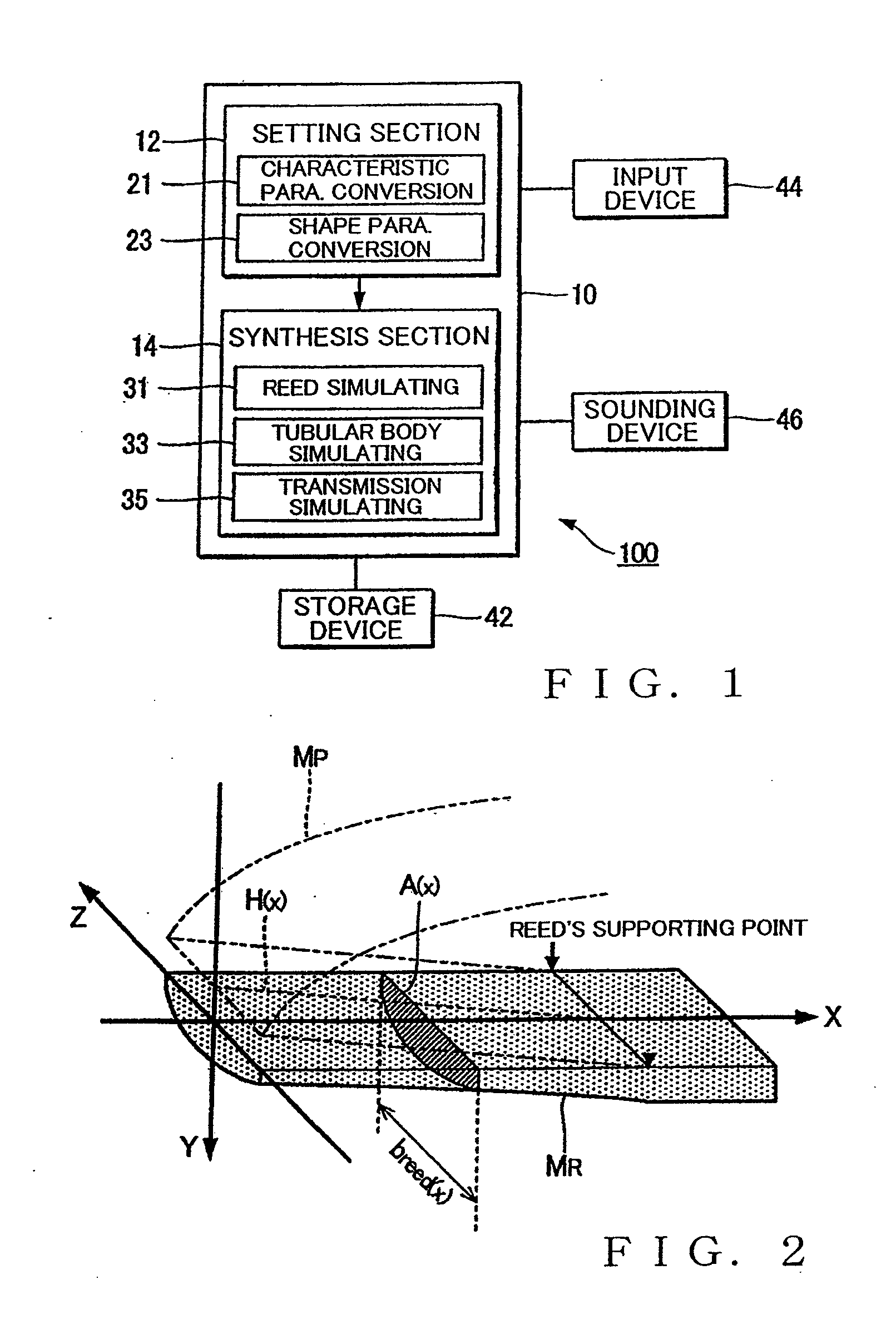
[0034]FIG. 1 is a block diagram showing an example setup of a first embodiment of a tone synthesis apparatus of the present invention. This tone synthesis apparatus 100 is constructed to synthesize tones by simulating, through arithmetic operations, the tone generating principles of a single-reed wind instrument, such as a saxophone or clarinet. As shown in FIG. 1, the tone synthesis apparatus 100 is implemented by a computer system that comprises an arithmetic operation processing device 10, a storage device 42 and a sounding device 46.

[0035]The arithmetic operation processing device, such as a CPU (Central Processing Unit) 10, executes programs, stored in the storage device 42, to generate and output tone data representative of a time-varying waveform of a wind instrument (i.e., temporal variation of sound pressure). The storage device 42 stores therein programs for execution by the arithmetic operation processing device 10 and data for use by the arithmetic operation processing d...

second embodiment

[0131]Next, a description will be given about a second embodiment of the present invention. Whereas the first embodiment has been described above in relation to the case where the spring constant klip(x) does not depend on the pressing force flip(x) from the teeth MT, the second embodiment uses a spring constant klip(x) (x, flip(x)) that depends on the pressing force flip(x). In the following description of the second and other embodiments, similar elements to those in the first embodiment are indicated by the same reference numerals and characters as used for the first embodiment and description of these similar elements are omitted here as necessary to avoid unnecessary duplication.

[0132]Relationship between the spring constant klip(x) (x, flip(x)) of the lip ML and the pressing force flip(x) is determined through actual measurement. FIG. 14 is a diagram explanatory of how the spring constant klip(x) (x, flip(x)) is measured. As shown in FIG. 14, an outer surface of a test piece 8...

third embodiment

[0138]In the above-described first embodiment, the internal resistance μlip(x) of the lip ML and the internal resistance μreed(x) of the reed MR take fixed values that do not depend on the position x. However, in a third embodiment to be described below, the internal resistance μlip(x) of the lip ML and the internal resistance μreed(x) of the reed MR are varied in accordance with the position x.

[0139]If the horizontal width blip—sample of the lip sample in Mathematical Expression (a3) above is substituted by a horizontal width blip(x) corresponding to the position x, the following Mathematical Expression (a3-1) is derived:

μlip(x)=tanδlipmlip(x)·klip(x)=tanδlipρlip·blip(x)·dlip(x)·Elipblip(x)dlip(x)=tanδlip·blip(x)·ρlip·Elip(a3-1)

[0140]Similarly, for the internal resistance μreed(x) of the reed MR, there can be derived the following Equation (a4-1) where the sectional area A(x) of the reed MR that varies in accordance with the position x and the spring constant kreed(x) are variables...


PUM


Abstract

Tone synthesis apparatus synthesizes a tone of a wind instrument generated in response to vibration of a reed contacting a lip during a performance of the wind instrument. First arithmetic operation section solves a motion equation representative of behavior of the reed in an equilibrium state with external force acting on the lip and a second motion equation representative of behavior of the lip in the equilibrium state, to thereby calculate displacement yb(x), y0(x) of the lip and reed in the equilibrium state. Second arithmetic operation section solves a motion equation of coupled vibration of the lip and reed with calculation results of the first arithmetic operation section used as initial values of the displacement yb(x), y0(x) of the lip and reed, to thereby calculate the displacement y(x, t) of the reed. Tone is synthesized on the basis of the displacement y(x, t) calculated by the second arithmetic operation section.

Description

BACKGROUND[0001]The present invention relates to a technique for synthesizing tones of wind instruments that generate tones in response to vibration of a reed.[0002]Heretofore, there have been proposed tone synthesis apparatus of a physical model type (i.e., physical model tone generators) for synthesizing tones by simulating the tone generating principles of musical instruments. Among such tone synthesis apparatus are techniques disclosed in R. T. Schumacher “Ab Initio Calculations of the Oscillations of a Clarinet”, ACUSTICA, 1981, Volume 48 No. 2, p. 75-p. 85 (hereinafter referred to as Non-patent Literature 1); and S. D. Sommerfeldt, W. J. Strong, “Simulation of a player-clarinet system”, Acoustical Society of America, 1988, 83(5), p. 1908-p. 1918 (hereinafter referred to as Non-patent Literature 2). More specifically, Non-patent Literature 1 discloses a technique for simulating behavior of a clarinet by modeling a reed as a rigid air valve freely movable in its entirety, and No...

Claims


Application Information

Patent Timeline
Patent Type & Authority Applications(United States)
IPC IPC(8): G10H7/00
CPCG10H5/007
Inventor MASUDA, HIDEYUKI
Owner YAMAHA CORP
Why Eureka
Try Eureka