Fuel supply systems
- Summary
- Abstract
- Description
- Claims
- Application Information
AI Technical Summary
Benefits of technology
Problems solved by technology
Method used
Image

Examples
first embodiment
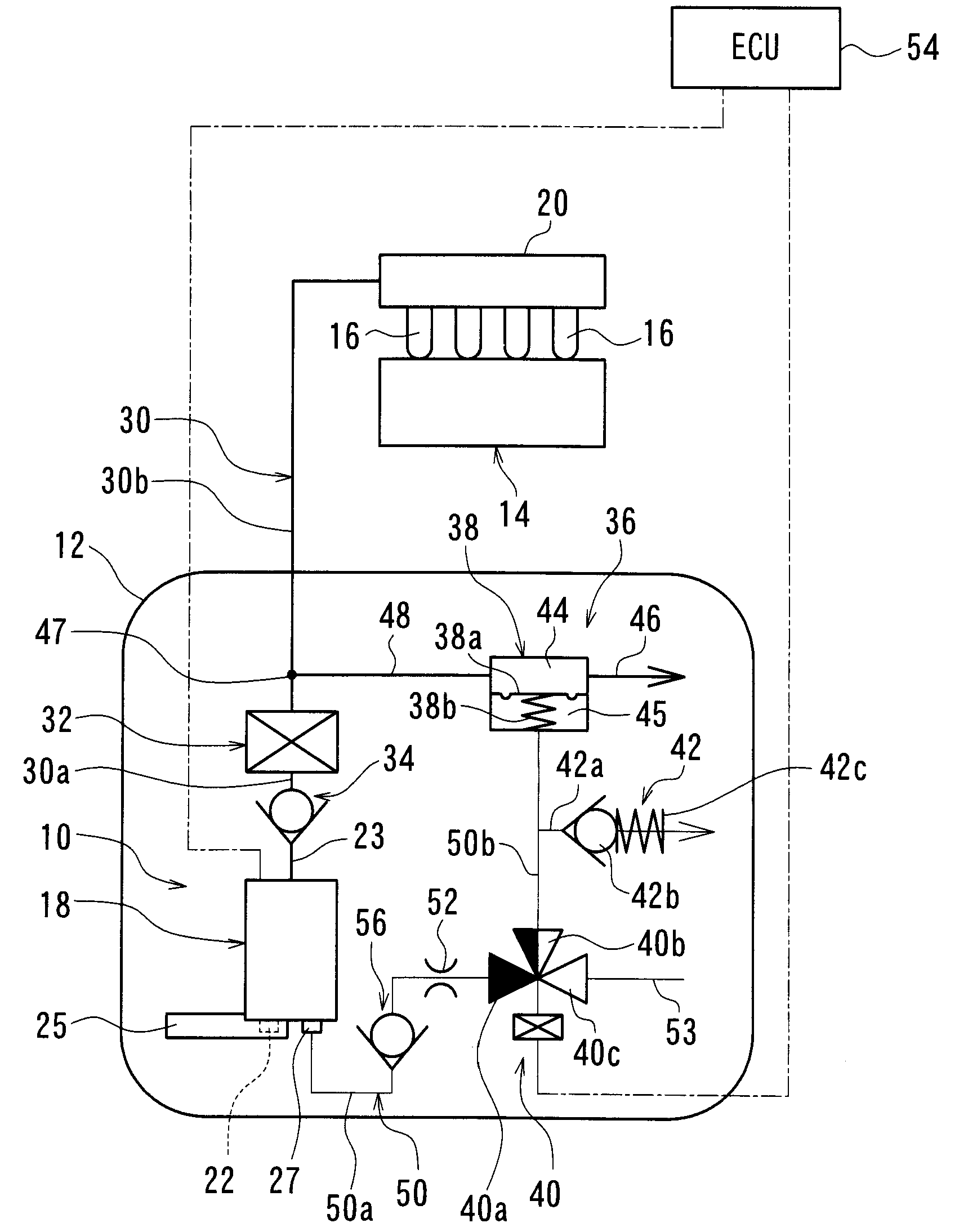
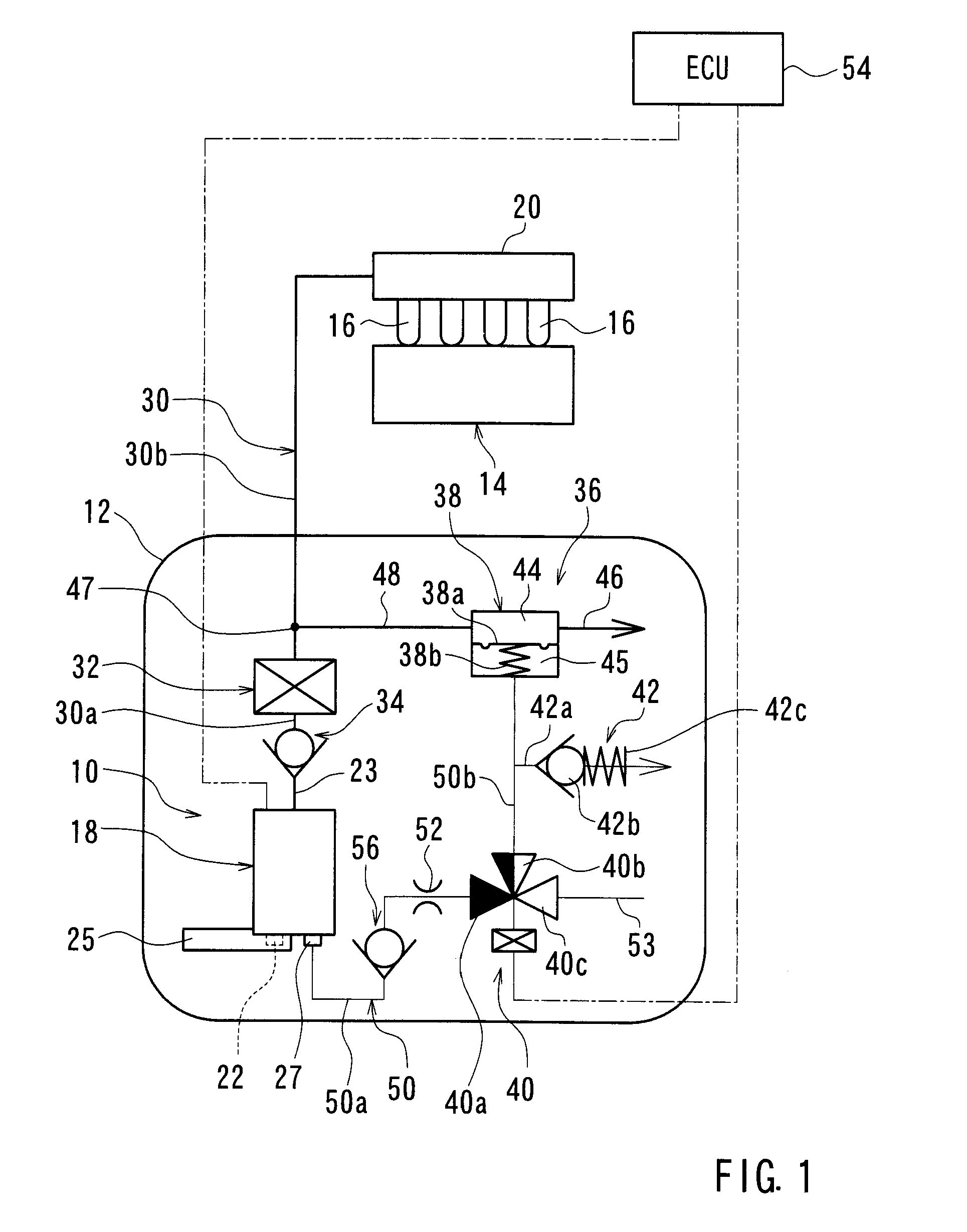
[0041]A first embodiment of the present invention will now be described. This embodiment relates to a fuel supply system used in a vehicle engine. FIG. 1 is a schematic diagram illustrating the fuel supply system.
[0042]Referring to FIG. 1, a fuel supply system 10 is equipped with a fuel pump 18. The fuel pump 18 can supply fuel stored in a fuel tank 12 to fuel injection valves (injectors) 16 respectively corresponding to cylinders of an engine 14. The fuel tank 12 is mounted to a vehicle (not shown). The fuel injection valves 16 are mounted to a delivery pipe 20. The fuel pump 18 may be a motor driven pump, such as a turbine type electric pump that includes a motor serving as an electric drive section and a pump section having an impeller rotatably driven by the motor for pressurizing fuel drawn into the fuel pump 18. The fuel pump 18 may be installed in the fuel tank 12. The fuel pump 18 draws the fuel in the fuel tank 12 from a fuel inlet port 22 and pressurizes the fuel before di...
second embodiment
[0065]A second embodiment of the present invention will now be described with reference to FIGS. 4 and 5. Since this embodiment is obtained by partially modifying the first embodiment described above, members that are the same or similar to the members of the first embodiment are labeled with the same reference numerals as the first embodiment and an explanation of these members will not be repeated. FIG. 4 is a schematic diagram showing the construction of a fuel supply system of the second embodiment.
[0066]As shown in FIG. 4, in this embodiment, the upstream side end portion of the upstream side path 50a of the back pressure introduction path 50 of the first embodiment (See FIG. 1) described above is connected to the diverting portion (indicated by numeral 58) of the pressure regulating and introduction path 48 instead of connecting it to the vapor discharge port 27 of the fuel pump 18. As result, a portion of the fuel (pressurized fuel) flowing through the pressure regulating and...
third embodiment
[0076]A third embodiment of the present invention will be described. Since this embodiment is realized by partially modifying the second embodiment, the following description will be focused mainly on the modified portion. FIG. 7 is a schematic diagram showing the construction of a fuel supply system of the third embodiment.
[0077]As shown in FIG. 7, in this embodiment, the electromagnetic valve 60 of the second embodiment (See FIG. 4) is omitted, and a fluid valve 62 is provided in the atmospheric pressure path 53. The fluid valve 62 may be an opening and closing valve driven by a fluid pressure. In this embodiment fluid valve 62 is opened and closed by the pressure of surplus fuel (return fuel) discharged from the pressure regulating chamber 44 of the pressure regulator 38 via the return fuel path 46. The fluid valve 62 is a valve device that can open and close the atmospheric pressure side path (the atmospheric pressure path 53) of the change-over valve 40 of the change-over devic...
PUM
 Abstract
Description
Claims
Application Information
 - Generate Ideas
- Intellectual Property
- Life Sciences
- Materials
- Tech Scout
- Unparalleled Data Quality
- Higher Quality Content
- 60% Fewer Hallucinations
Browse by: Latest US Patents, China's latest patents, Technical Efficacy Thesaurus, Application Domain, Technology Topic, Popular Technical Reports.
© 2025 PatSnap. All rights reserved.Legal|Privacy policy|Modern Slavery Act Transparency Statement|Sitemap|About US| Contact US: help@patsnap.com