
Vapor chamber with wick structure of different thickness and die for forming the same

Inactive Publication Date: 2010-07-15
CELSIA TECH TAIWAN INC
View PDF12 Cites 7 Cited by
  • Summary
  • Abstract
  • Description
  • Claims
  • Application Information

AI Technical Summary

Benefits of technology

[0009]The present invention is to provide a vapor chamber with a wick structure of different thickness and a die for forming the vapor chamber so as to increase the heat-conducting efficiency and reduce the cost.
[0012]In comparison with prior art, according to the present invention, the first wick section of the wick structure has a larger thickness while the second wick section has a smaller thickness. Via this arrangement, the present invention has effects of improving the heat-conducting efficiency and reducing the cost. In this way, the drawbacks of prior art can be overcome.

Problems solved by technology

However, in practice, the conventional vapor chamber still has some drawbacks as follows.
Thus, in this case, the heat-conducting efficiency is poor.
The utilization ratio of the second wick structure is low, which may waste the material and increase the cost.

Method used


Image

  • Vapor chamber with wick structure of different thickness and die for forming the same
  • Vapor chamber with wick structure of different thickness and die for forming the same
  • Vapor chamber with wick structure of different thickness and die for forming the same

Examples


Embodiment Construction

[0024]The detailed description and technical contents of the present invention will be explained with reference to the accompanying drawings. However, the drawings are illustrative only but not used to limit the present invention.

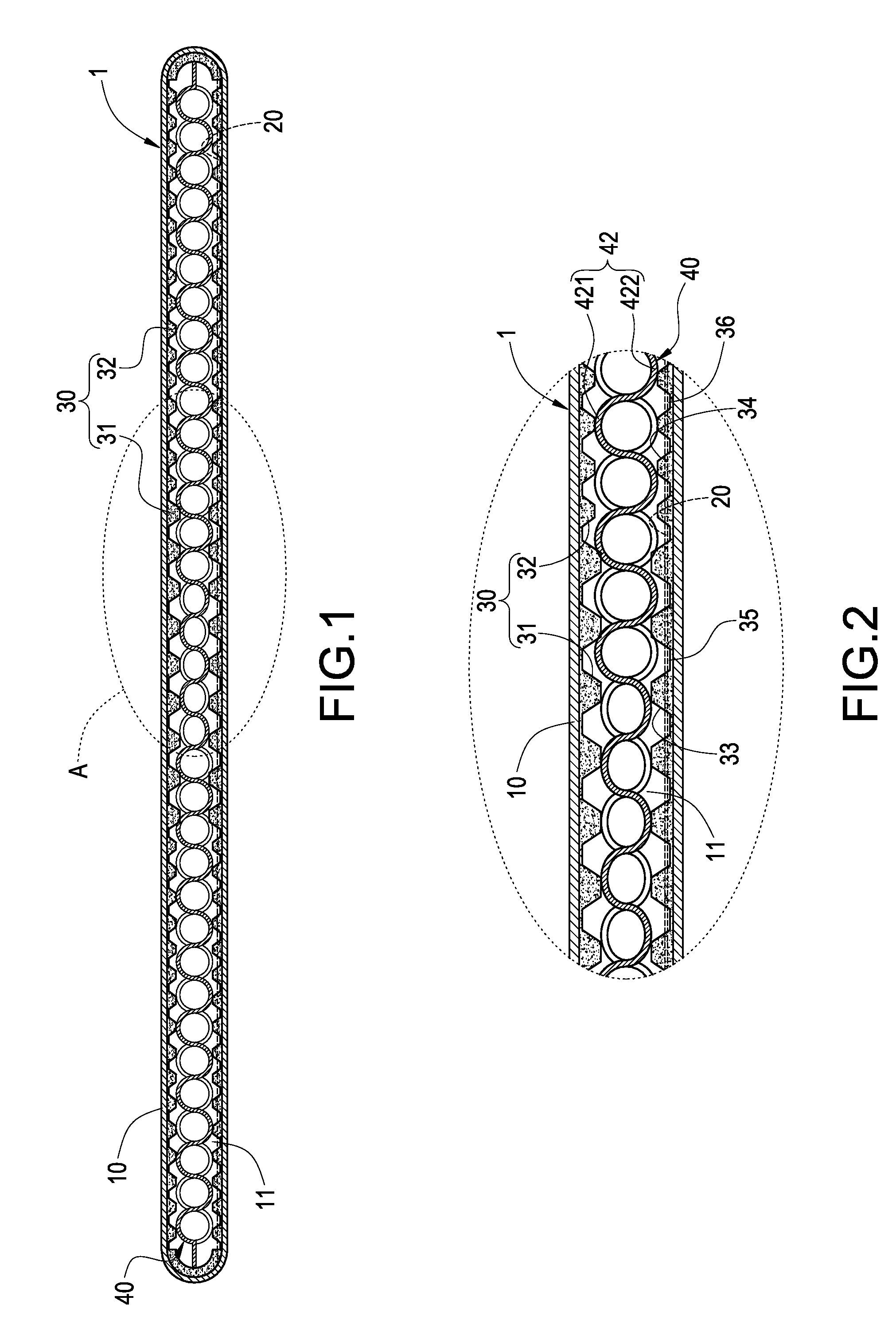
[0025]Please refer to FIGS. 1 and 2. The present invention provides a vapor chamber 1 with a wick structure of different thickness, which is constituted of a casing 10, a working fluid 20, a wick structure 30 and a supporting body 40.

[0026]The casing 10 is made of copper or aluminum. The interior of the casing 10 is formed with a chamber 11.

[0027]The working fluid 20 is filled in the chamber 11. The working fluid 20 can be pure water, alcohol, methanol, ethanol or propyl alcohol, but it is not limited thereto.

[0028]The wick structure 30 is adhered to the inner wall of the chamber 11. The wick structure 30 has a first wick section 31 and a second wick section 32 extending from the first wick section 31. The thickness of the wick section 31 is larger than tha...


PUM

PropertyMeasurementUnit
Thicknessaaaaaaaaaa
Structureaaaaaaaaaa
Depthaaaaaaaaaa

Abstract

A vapor chamber with a wick structure of different thickness includes a casing, a wick structure, a supporting body and a working fluid. The casing has a chamber. The wick structure is adhered to the inner wall of the chamber. The wick structure has a first wick section and a second wick section extending from the first wick structure. The thickness of the first wick section is larger than that of the second wick section. The supporting body is received within the wick structure. The working fluid is filled within the chamber. Via the above arrangement, the heat-conducting efficiency can be increased while the cost can be reduced.

Description

BACKGROUND OF THE INVENTION[0001]1. Field of the Invention[0002]The present invention relates to a vapor chamber and a die for forming the vapor chamber, and in particular to a vapor chamber with a wick structure of different thickness and a die for forming the vapor chamber.[0003]2. Description of Prior Art[0004]Since vapor chambers have many advantageous features such as large heat-conducting capacity, high heat-transferring rate, light weight, simple structure, versatility, capability of transferring large amount of heat without consuming any electricity, low price and etc., they are widely used in dissipating the heat generated by electronic elements. Via the vapor chamber, the heat generated by electronic elements can be dissipated quickly, thereby overcoming the heat accumulation occurring in the electronic elements at current stage.[0005]The conventional vapor chamber includes a casing, a wick structure, a supporting body and a working fluid. The casing has a chamber. The wic...

Claims


Application Information

Patent Timeline
IPC IPC(8): F28D15/00B21D22/00
CPCB22F7/004B22F2998/00F28D15/046B22F3/1283
Inventor MEYER, IV, GEORGE ANTHONYSUN, CHIEN-HUNGCHEN, CHIEH-PING
Owner CELSIA TECH TAIWAN INC
Learn More