

Heat-conducting assembly for heat pipes of different diameters and heat sink having the same
- Summary
- Abstract
- Description
- Claims
- Application Information
AI Technical Summary
Benefits of technology
Problems solved by technology
Method used
Image

Examples
Embodiment Construction
[0019]The characteristics and technical contents of the present invention will be described with reference to the accompanying drawings. However, the drawings are illustrative only but not used to limit the present invention.
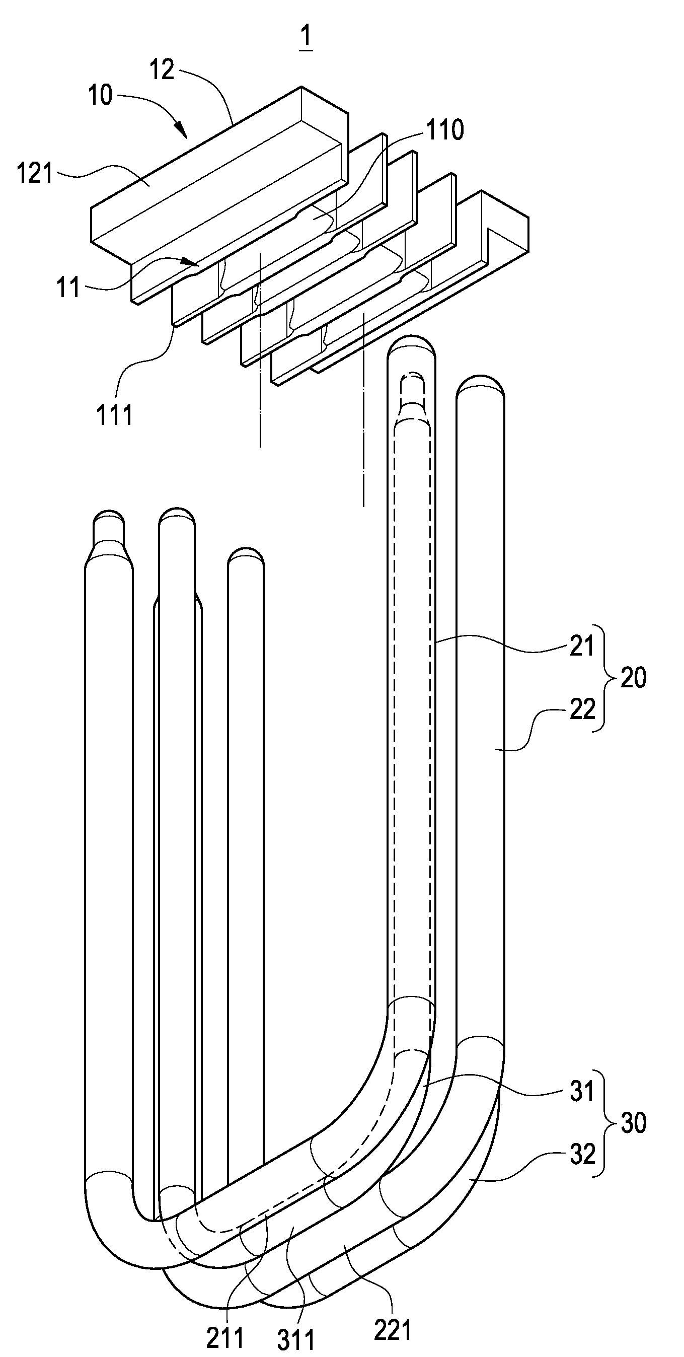
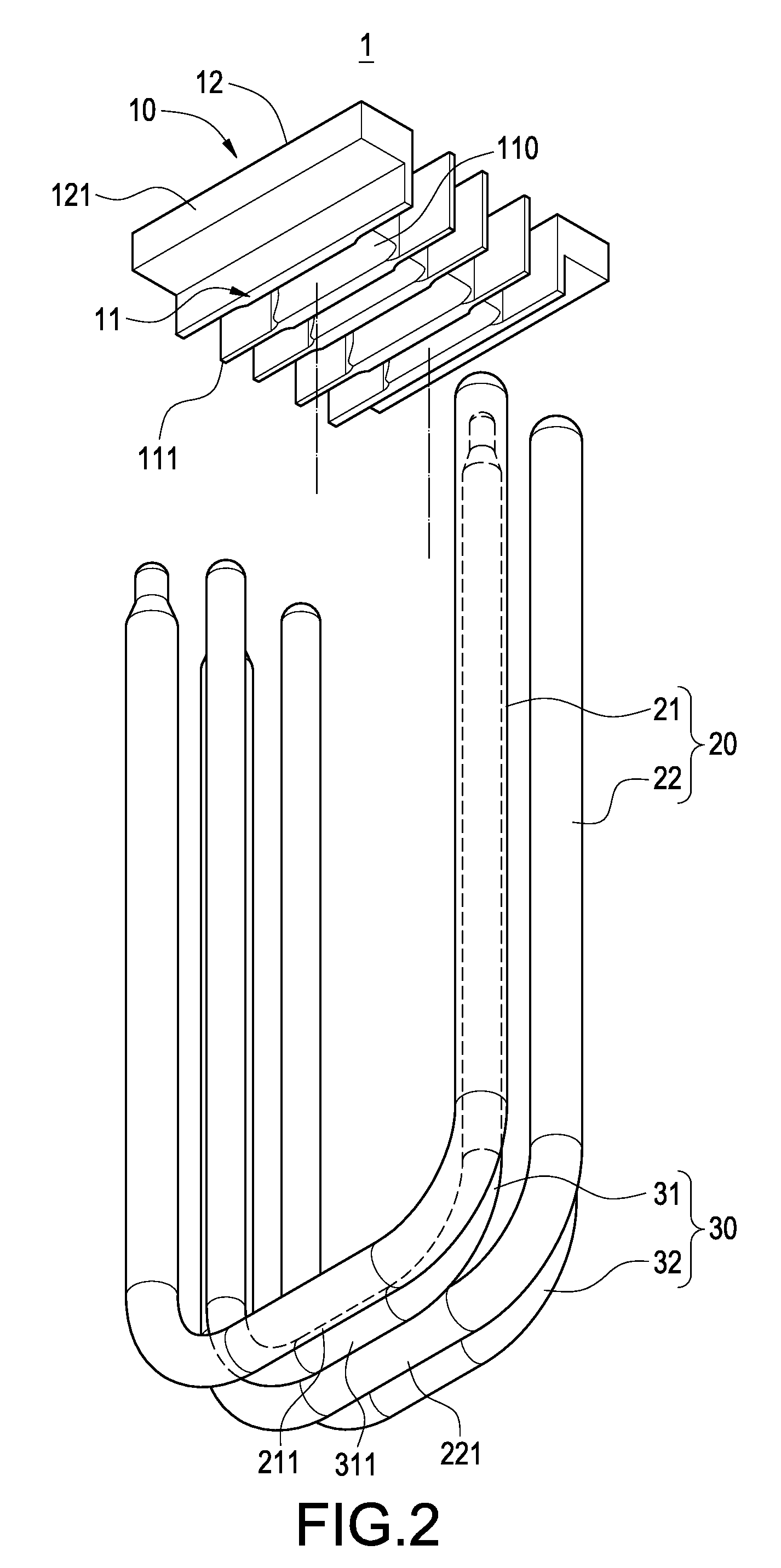
[0020]Please refer to FIGS. 2 and 3. FIG. 2 is an exploded perspective view showing the heat-conducting assembly of the present invention. FIG. 3 is an assembled perspective view showing the heat-conducting assembly of the present invention. The present invention provides a heat-conducting assembly 1 for heat pipes of different diameters, which includes a heat-conducting base 10, a set 20 of first heat pipes and a set 30 of second heat pipes.
[0021]The bottom surface of the heat-conducting base 10 acts as a heat-conducting surface 11. The heat-conducting surface 11 is provided with a plurality of accommodating troughs 110. A partition 111 is formed between the respective accommodating troughs 110. Further, a fixing wing 121 extends from each side of a top surface...
PUM
 Abstract
Description
Claims
Application Information