
Single pump focused sampling

a single-piston, sampling technology, applied in the direction of survey, fluid removal, borehole/well accessories, etc., can solve the problems of affecting significant financial expenditures and/or savings, fluid that is generally unacceptable for hydrocarbon fluid sampling and/or evaluation, and various challenges

Inactive Publication Date: 2010-07-15
SCHLUMBERGER TECH CORP
View PDF100 Cites 46 Cited by
  • Summary
  • Abstract
  • Description
  • Claims
  • Application Information

AI Technical Summary

Problems solved by technology

This aspect of the exploration and recovery process can be crucial in developing drilling strategies, and can impact significant financial expenditures and / or savings.
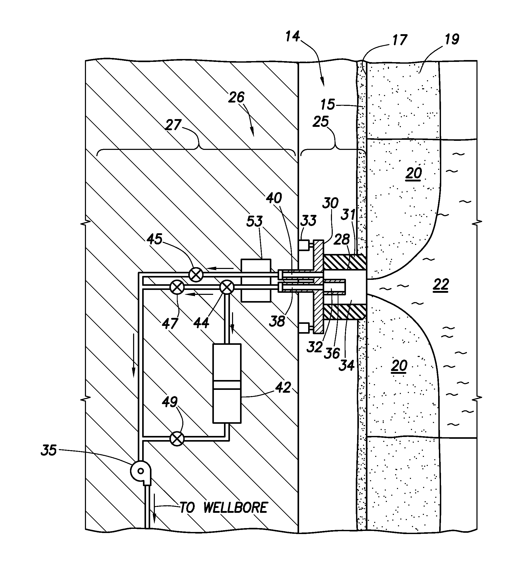
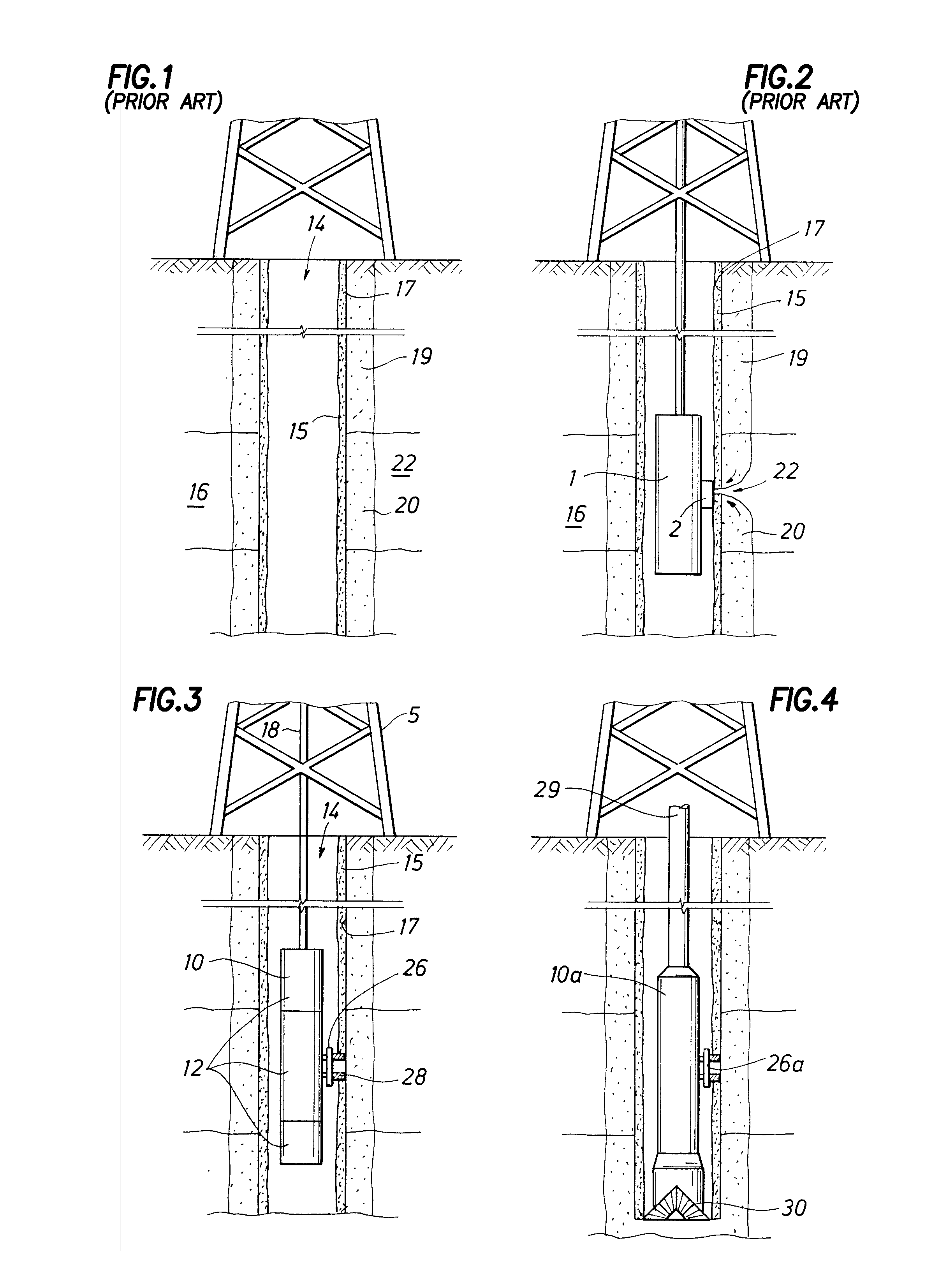
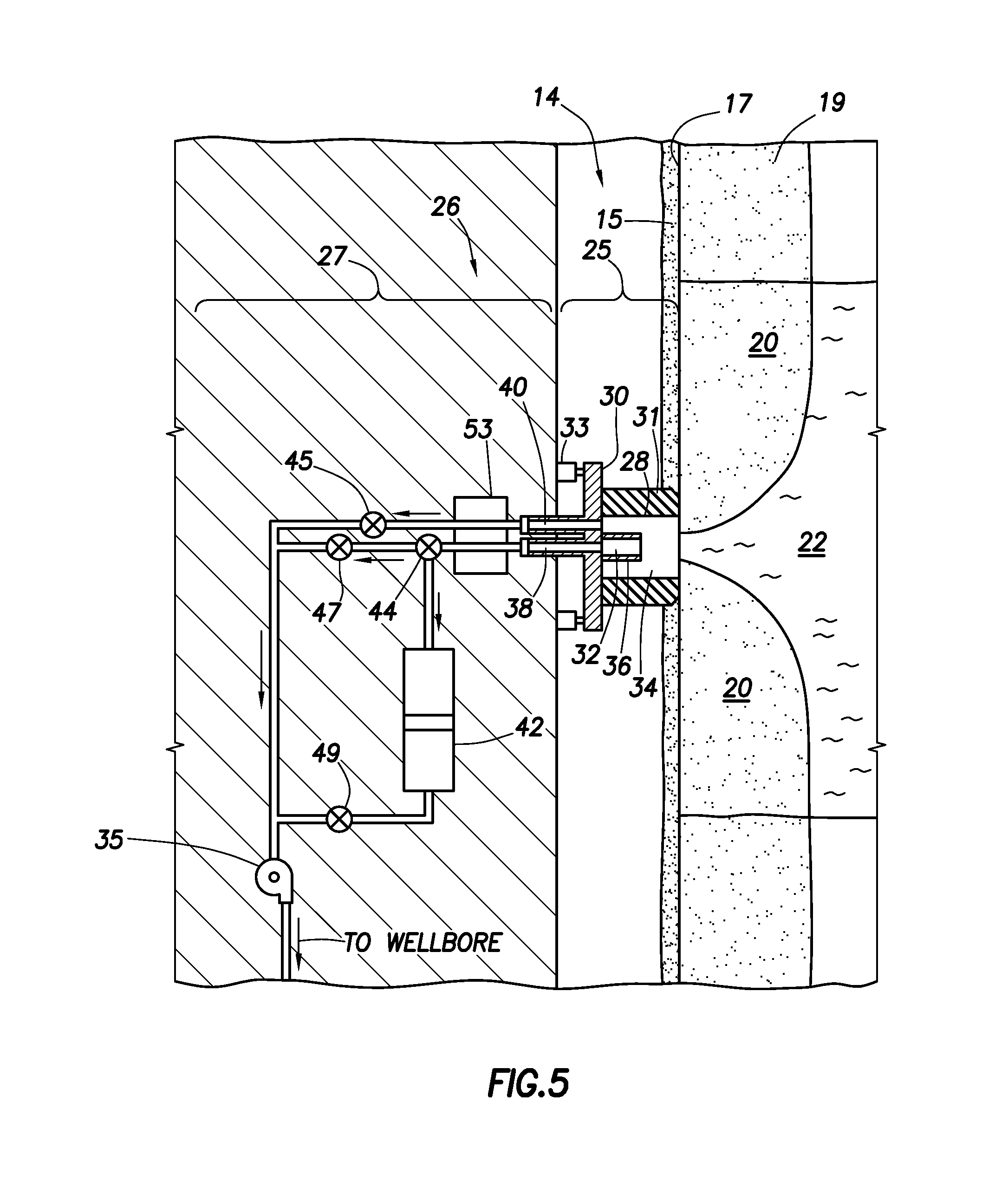
Various challenges may arise in the process of obtaining virgin fluid from subsurface formations.
This material often contaminates the virgin fluid as it passes through the borehole, resulting in fluid that is generally unacceptable for hydrocarbon fluid sampling and / or evaluation.
Such fluid is referred to herein as “contaminated fluid.” Because fluid is sampled through the borehole, mudcake, cement and / or other layers, it is difficult to avoid contamination of the fluid sample as it flows from the formation and into a downhole tool during sampling.
A challenge thus lies in minimizing the contamination of the virgin fluid during fluid extraction from the formation.
The challenge remains in adapting to the flow of the fluid so that the virgin fluid is collected in the downhole tool during sampling.
However, it has been discovered that when the formation fluid passes into the downhole tool, various contaminants, such as wellbore fluids and / or drilling mud, may enter the tool with the formation fluids.
These contaminates may affect the quality of measurements and / or samples of the formation fluids.
Moreover, contamination may cause costly delays in the wellbore operations by requiring additional time for more testing and / or sampling.
Additionally, such problems may yield false results that are erroneous and / or unusable.

Method used


Image

  • Single pump focused sampling
  • Single pump focused sampling
  • Single pump focused sampling

Examples


Embodiment Construction

[0055]It is to be understood that the following disclosure provides many different embodiments, or examples, for implementing different features of various embodiments. Specific examples of components and arrangements are described below to simplify the present disclosure. These are, of course, merely examples and are not intended to be limiting. In addition, the present disclosure may repeat reference numerals and / or letters in the various examples. This repetition is for the purpose of simplicity and clarity and does not in itself dictate a relationship between the various embodiments and / or configurations discussed. Moreover, the formation of a first feature over or on a second feature in the description that follows may include embodiments in which the first and second features are formed in direct contact, and may also include embodiments in which additional features may be formed interposing the first and second features, such that the first and second features may not be in d...


PUM


Abstract

An apparatus comprising first and second fluid intakes, a pump, and a sample chamber, may be positioned in a borehole penetrating a subterranean formation. A method of use thereof may comprise drawing fluid from the subterranean formation and into the first and second fluid intakes using the pump, discharging into the borehole at least a portion of the fluid drawn into the second fluid intake, and selectively diverting at least a portion of the fluid drawn into the first fluid intake to the sample chamber.

Description

CROSS-REFERENCE TO RELATED APPLICATIONS[0001]This application is a continuation-in-part of U.S. patent application Ser. No. 11 / 609,384, filed on Dec. 12, 2006, which is a continuation-in-part of U.S. Pat. No. 7,484,563, which is a continuation-in-part of U.S. Pat. Nos. 7,178,591 and 7,090,012. U.S. Pat. No. 7,090,012 is a divisional of U.S. Pat. No. 6,964,301.[0002]This application is also related to commonly-assigned U.S. patent application Ser. No. 12 / 340,218, entitled “FORMATION EVALUATION SYSTEM AND METHOD,” filed Dec. 19, 2008, the disclosure of which is hereby incorporated herein by reference.BACKGROUND OF THE DISCLOSURE[0003]Wellbores are drilled to locate and produce hydrocarbons. A downhole drilling tool with a bit at an end thereof is advanced into the ground to form a wellbore. As the drilling tool is advanced, a drilling mud is pumped through the drilling tool and out the drill bit to cool the drilling tool and carry away cuttings. The fluid exits the drill bit and flows...

Claims


Application Information

Patent Timeline
IPC IPC(8): E21B49/08E21B43/00
CPCE21B49/008E21B49/10G01N33/0009G01N1/24E21B49/081E21B49/08
Inventor MILKOVISCH, MARKZAZOVKSY, ALEXANDERROSS, SIMON
Owner SCHLUMBERGER TECH CORP
Learn More