Patch antenna

a technology of patch antenna and antenna body, applied in the field of patch antenna, can solve the problem of inferior response characteristic, and achieve the effect of improving the omnidirectional response pattern and keeping the design fla

Inactive Publication Date: 2010-07-15
WILHELM SIHN JR
View PDF4 Cites 8 Cited by
  • Summary
  • Abstract
  • Description
  • Claims
  • Application Information

AI Technical Summary

Benefits of technology

[0004]A patch antenna according to the invention comprises a reflector that surrounds the dielectric and that opens progressively in a direction away from the ground plane toward the radiator plane. The area enclosed by the reflector therefore increases in proportion to the rising distance from the ground plane. It is possible in this way to improve the omnidirectional response pattern while at the same time keeping the design flat.

Problems solved by technology

However, flat patch antennas, which can be mounted for example below a glass roof or a plastic roof of a motor vehicle, normally have a response characteristic inferior to that of turnstile antennas or quadrifilar helix antennas, for example, in an angular range of 50° to 70° elevation.

Method used


Image

  • Patch antenna
  • Patch antenna

Examples


Embodiment Construction

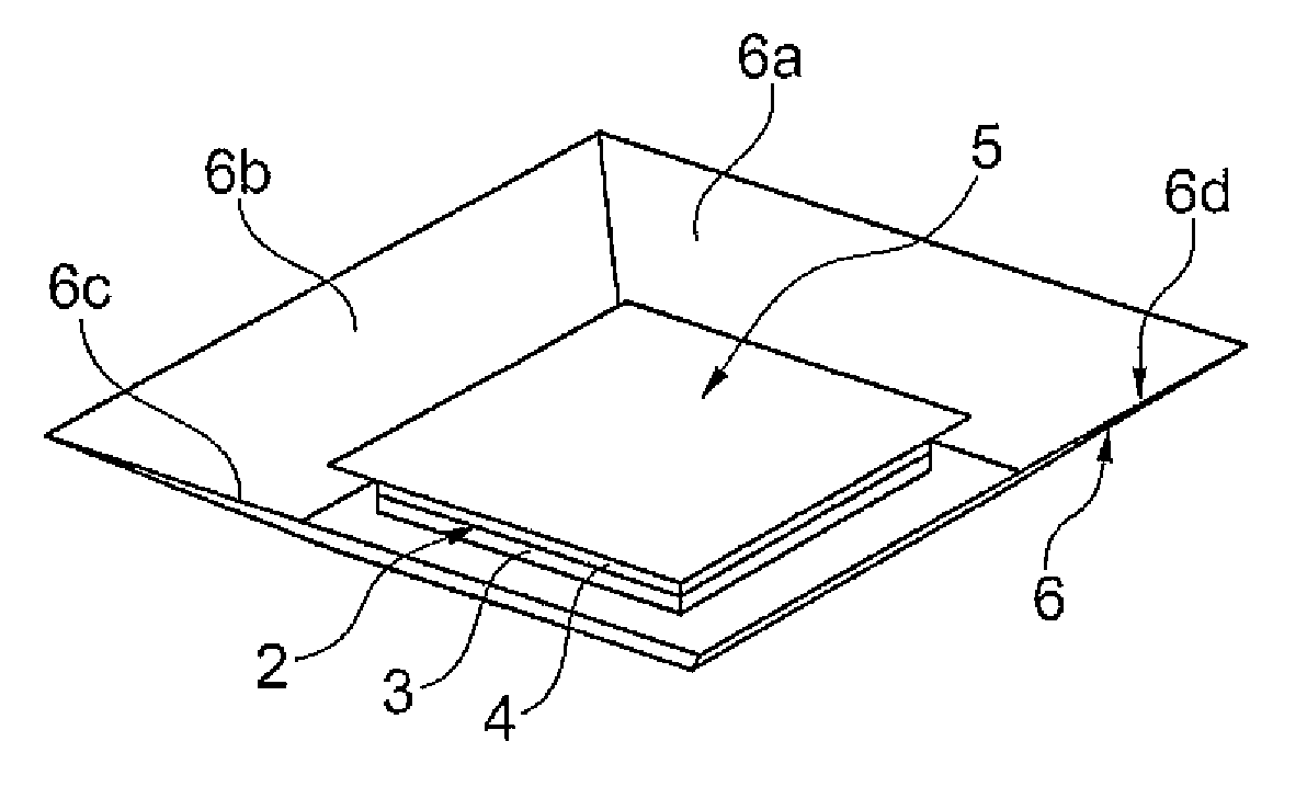
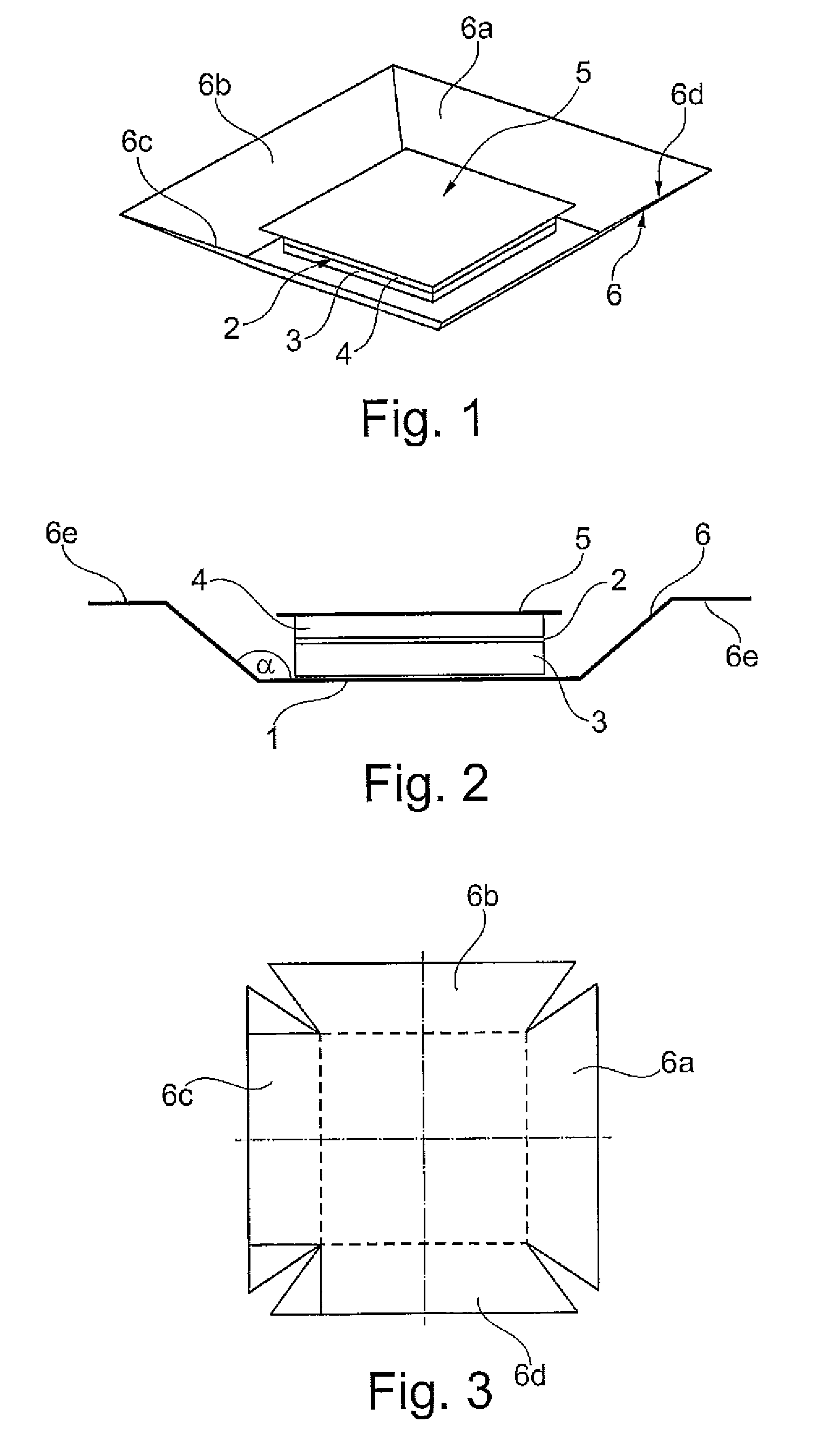
[0013]The patch antenna illustrated in FIGS. 1 and 2 has an electrically conductive ground plane 1, an electrically conductive radiator plane 2 and a dielectric 3 material arranged between the ground plane and the radiator plane. An additional dielectric layer 4 with an additional radiator plane 5, forming a stray radiator element, are arranged on the radiator plane 2.

[0014]The dielectric 3 is surrounded by a reflector 6 which opens progressively in a direction away from the ground plane 1 toward the radiator plane 2. The reflector 6 has four reflector surfaces 6a, 6b, 6c, 6d, which extend obliquely relative to the ground plane 1 and which accordingly show the form of a truncated pyramid. The reflector surfaces 6a, 6b, 6c, 6d and the ground plane 1 enclose between them an angle α of 120° to 150°, especially of 130° to 140°. In the illustrated embodiment, the angle α is 135°.

[0015]As can be seen especially in FIG. 2, the reflector 6 extends beyond the radiator plane 2, and also beyon...


PUM


Abstract

A patch antenna includes an electrically conductive ground plane, an electrically conductive radiator plane, a dielectric arranged between the ground plane and the radiator plane, and a reflector which surrounds the dielectric and which progressively opens in a direction away from the ground plane toward the radiator plane.

Description

[0001]The present invention relates to a patch antenna. Patch antennas of that kind are known and are in use especially on automobiles.[0002]Patch antennas advantageously can be made small and compact so that they are suited for being mounted on automobiles without impairing their aesthetic appearance. However, flat patch antennas, which can be mounted for example below a glass roof or a plastic roof of a motor vehicle, normally have a response characteristic inferior to that of turnstile antennas or quadrifilar helix antennas, for example, in an angular range of 50° to 70° elevation.[0003]An object of the invention is therefore to show how the response characteristics of a patch antenna of the before-mentioned kind can be improved, especially in the stated angular range.SUMMARY OF THE INVENTION[0004]A patch antenna according to the invention comprises a reflector that surrounds the dielectric and that opens progressively in a direction away from the ground plane toward the radiator...

Claims


Application Information

Patent Timeline
Patent Type & Authority Applications(United States)
IPC IPC(8): H01Q19/12
CPCH01Q1/3275H01Q19/106H01Q19/005H01Q9/0407
Inventor BASHIR, MOHAMMAD
Owner WILHELM SIHN JR
Why Eureka
Try Eureka