Pillar structure and vehicle side portion structure

a technology of pillars and side panels, applied in the direction of roofs, transportation and packaging, vehicle arrangements, etc., can solve the problems of deformation of outer panels and inner panels, and achieve the effect of preventing design from being marred, superior effect, and superior

Active Publication Date: 2015-10-15
TOYOTA JIDOSHA KK
View PDF16 Cites 5 Cited by
  • Summary
  • Abstract
  • Description
  • Claims
  • Application Information

AI Technical Summary

Benefits of technology

[0031]As described above, according to the first aspect and the seventh aspect of the present invention, the invention has the superior effect that the joint state of the pillar structure can be well maintained during a side impact.
[0032]According to the second aspect of the present invention, the invention has the superior effects that the joint state of the pillar structure can be well maintained during a side impact and the design can be kept from being marred.
[0033]According to the third aspect and the fourth aspect of the present invention, the invention has the superior effect that deformation of the pillar structure during a side impact can be controlled.
[0034]According to the fifth aspect of the present invention, the invention has the superior effect that the joint state of the pillar structure can be better maintained during a side impact.
[0035]According to the sixth aspect of the present invention, the invention has the superior effect that the amount of time it takes to adjust the joint surfaces can be shortened.

Problems solved by technology

However, when, during a side impact to the vehicle to which this pillar structure is applied, the impact load is input to the pillar structure, the outer panel and the inner panel become deformed in directions in which they move away from one another.

Method used


Image

  • Pillar structure and vehicle side portion structure
  • Pillar structure and vehicle side portion structure
  • Pillar structure and vehicle side portion structure

Examples


first embodiment

Vehicle Side Portion Structure

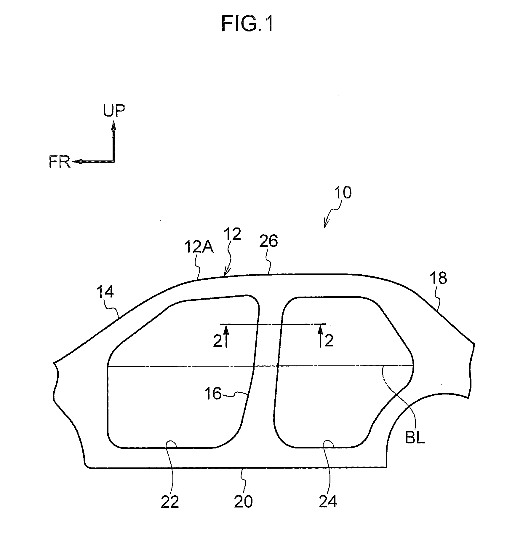
[0046]As shown in FIG. 1, a vehicle 12 to which a vehicle side portion structure 10 pertaining to a first embodiment of the present invention is applied is equipped with a front pillar 14 that is disposed on a front portion of a vehicle side portion 12A and extends in the vehicle up and down direction. Furthermore, a center pillar 16 that extends in the vehicle up and down direction is disposed on the vehicle rear side of the front pillar 14, and a rear pillar 18 that extends in the vehicle up and down direction is disposed on the vehicle rear side of the center pillar 16.

[0047]The lower end portion of the front pillar 14, the lower end portion of the center pillar 16, and the lower end portion of the rear pillar 18 are coupled to one another by a rocker 20 that extends in the vehicle front and rear direction. The rocker 20 configures the lower portion of the vehicle 12, and a front side door opening 22 for allowing an occupant to get into and out of th...

second embodiment

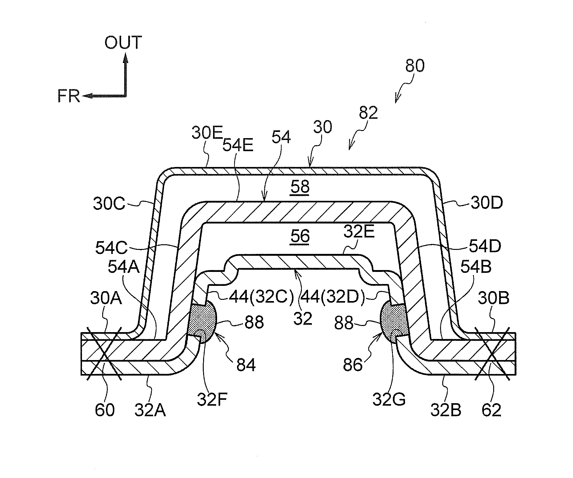
[0072]Next, a center pillar 50 to which a pillar structure 52 pertaining to a second embodiment of the present invention is applied will be described. It will be noted that regarding configurations that are the same as those of the first embodiment, the same reference signs will be assigned thereto and description thereof will be appropriately omitted. As shown in FIG. 4, the center pillar 50 pertaining to the present embodiment is mainly configured to include an outer panel 30, an inner panel 32, and a pillar outer reinforcement 54 that serves as a reinforcement member.

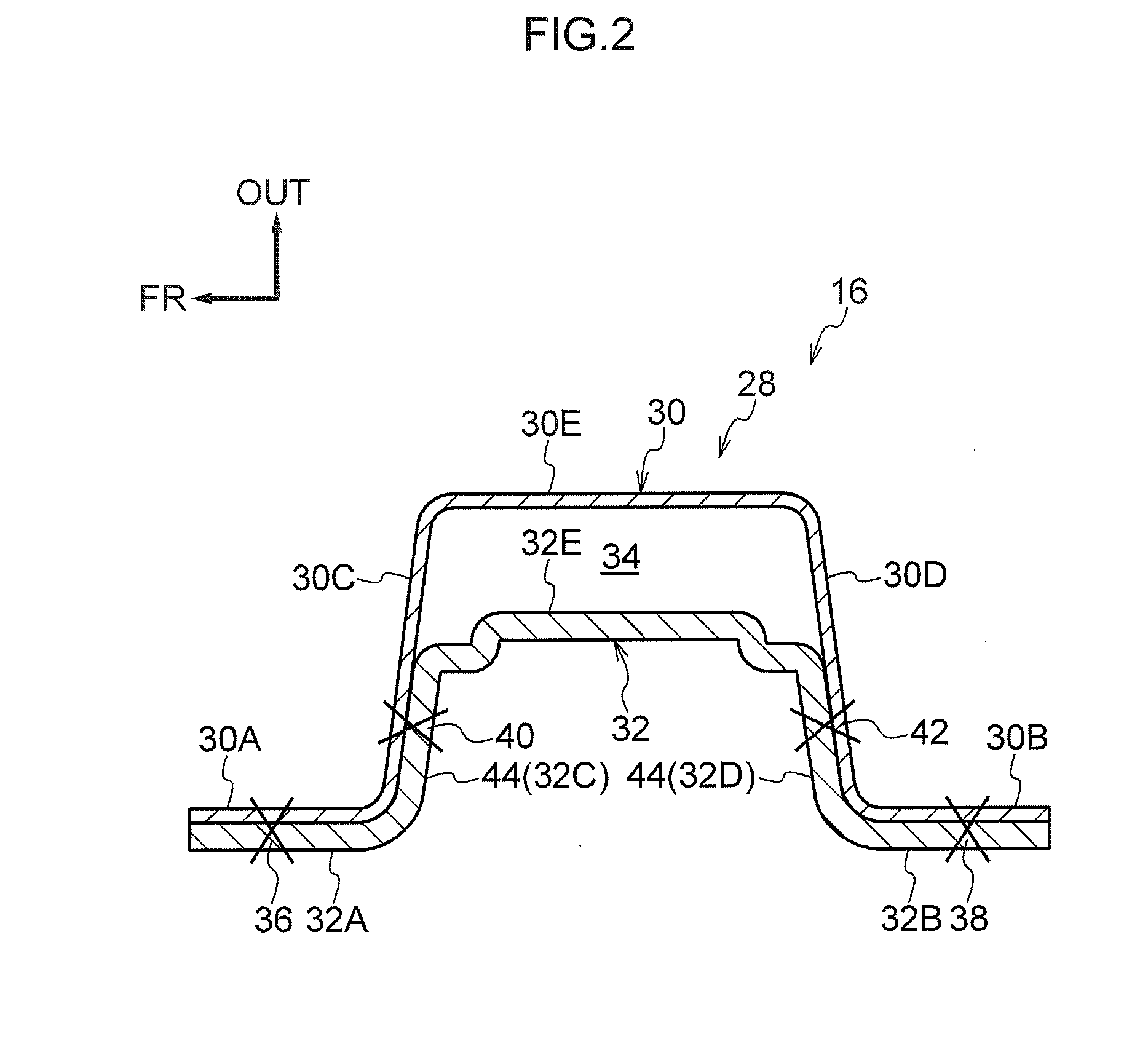
[0073]The outer panel 30 is formed in a cross-sectionally substantially hat shape and is equipped with a pair of outer flange portions 30A and 30B, a pair of outer longitudinal wall portions 30C and 30D, and an outer crown portion 30E. Furthermore, the inner panel 32 is formed in a cross-sectionally substantially hat shape, is disposed on the vehicle width direction inside of the outer panel 30, and is equipped with ...

third embodiment

[0083]Next, a center pillar 70 to which a pillar structure 72 pertaining to a third embodiment of the present invention is applied will be described. As shown in FIG. 5, the center pillar 70 pertaining to the present embodiment has the same configuration as the center pillar 50 pertaining to the second embodiment except for a longitudinal wall joint portion 74 and a longitudinal wall joint portion 76.

[0084]The longitudinal wall joint portion 74 is formed as a result of the reinforcement longitudinal wall portion 54C of the pillar outer reinforcement 54 and the inner longitudinal wall portion 32C of the inner panel 32 being joined (adhered) to one another by an adhesive 78. Furthermore, the longitudinal wall joint portion 76 is formed as a result of the reinforcement longitudinal wall portion 54D and the inner longitudinal wall portion 32D being joined (adhered) to one another by an adhesive 78.

[0085]According to the present embodiment, the step of performing welding such as spot wel...


PUM


Abstract

There is provided a pillar structure comprising: an outer panel that extends in a vehicle up and down direction and that is equipped with a pair of outer flange portions that extend in a vehicle front and rear direction, and outer longitudinal wall portions that extend outward in a vehicle width direction from the pair of outer flange portions; an inner panel that is disposed on a vehicle width direction inside of the outer panel and extends in the vehicle up and down direction along the outer panel and that is equipped with a pair of inner flange portions joined to the pair of outer flange portions, and inner longitudinal wall portions that extend outward in the vehicle width direction from the inner flange portions; and longitudinal wall joint portions formed by joining the outer longitudinal wall portions and the inner longitudinal wall portions to one another.

Description

CROSS-REFERENCE TO RELATED APPLICATION[0001]This application is based on and claims priority under 35 USC 119 from Japanese Patent Application No. 2014-083885 filed on Apr. 15, 2014, the disclosure of which is incorporated by reference herein.BACKGROUND[0002]1. Technical Field[0003]The present invention relates to a pillar structure and a vehicle side portion structure.[0004]2. Related Art[0005]As a pillar structure equipped with an outer panel and an inner panel, Japanese Patent Application Laid-Open (JP-A) No. 2011-251659 discloses a pillar structure where a cross-sectionally hat-shaped outer panel and a cross-sectionally hat-shaped inner panel are joined to one another at flange portions on both end portions. Furthermore, in the pillar structure of JP-A No. 2011-251659, a reinforcement member is disposed between the outer panel and the inner panel, and the reinforcement member is joined at flange portions to both the inner panel and the outer panel.[0006]However, when, during a s...

Claims


Application Information

Patent Timeline
Patent Type & Authority Applications(United States)
IPC IPC(8): B62D21/15B62D27/02B62D25/04
CPCB62D21/157B62D27/02B62D25/04
Inventor YOSHIDA, EIJI
Owner TOYOTA JIDOSHA KK
Why Eureka
Try Eureka