Rotation shaft supporting structure with journal bearing and assembling method of the bearing

a technology of supporting structure and bearing, which is applied in the direction of shaft and bearing, rotary bearing, bearing, etc., can solve the problems of mechanical efficiency decline, bearing seizure, overheating of the bearing surface of the tilting pad, etc., to prevent the occurrence of burning out of the bearing surface, favorable lubrication property, and lubrication of the bearing surface

Active Publication Date: 2010-07-15
MITSUBISHI HEAVY IND LTD
View PDF11 Cites 15 Cited by
  • Summary
  • Abstract
  • Description
  • Claims
  • Application Information

AI Technical Summary

Benefits of technology

The invention relates to a bearing design that prevents burning out of the bearing surface and reduces mechanical loss in lubrication. The bearing includes a journal with two oil supply nozzles that serve as stoppers to prevent circumferential movement of the pad, and a radial through hole in the bearing housing for adjusting the radial clearance between the bearing surface of the upper pad and the journal surface. These features improve the lubrication property of the bearing, prevent vibration and seizure, and reduce the need for separate means to prevent circumferential movement of the pad.

Problems solved by technology

The technical problem addressed in this patent text is the prevention of mechanical loss and bearing seizure in a tilting pad journal bearing. The patent describes various methods to prevent these issues, including the use of a direct lubrication type tilting pad journal bearing and the use of a spherical pivot to support the tilting pad. However, these methods require increased manufacturing costs and difficulty in adjusting the bearing clearance. The patent also discusses the formation of high pressure oil film in the oil film pressure distribution in the oil film pressure distribution in the bearing. The problem is to prevent carryover of lubrication oil in the oil film and to suppress the formation of high pressure oil film on the bearing surface. The patent proposes various methods to address these issues and improve the performance and cost-effectiveness of the tilting pad journal bearing.

Method used


Image

  • Rotation shaft supporting structure with journal bearing and assembling method of the bearing
  • Rotation shaft supporting structure with journal bearing and assembling method of the bearing
  • Rotation shaft supporting structure with journal bearing and assembling method of the bearing

Examples


Embodiment Construction

[0067]A preferred embodiment of the present invention will now be detailed with reference to the accompanying drawings. It is intended, however, that unless particularly specified, dimensions, materials, relative positions and so forth of the constituent parts in the embodiments shall be interpreted as illustrative only not as limitative of the scope of the present invention.

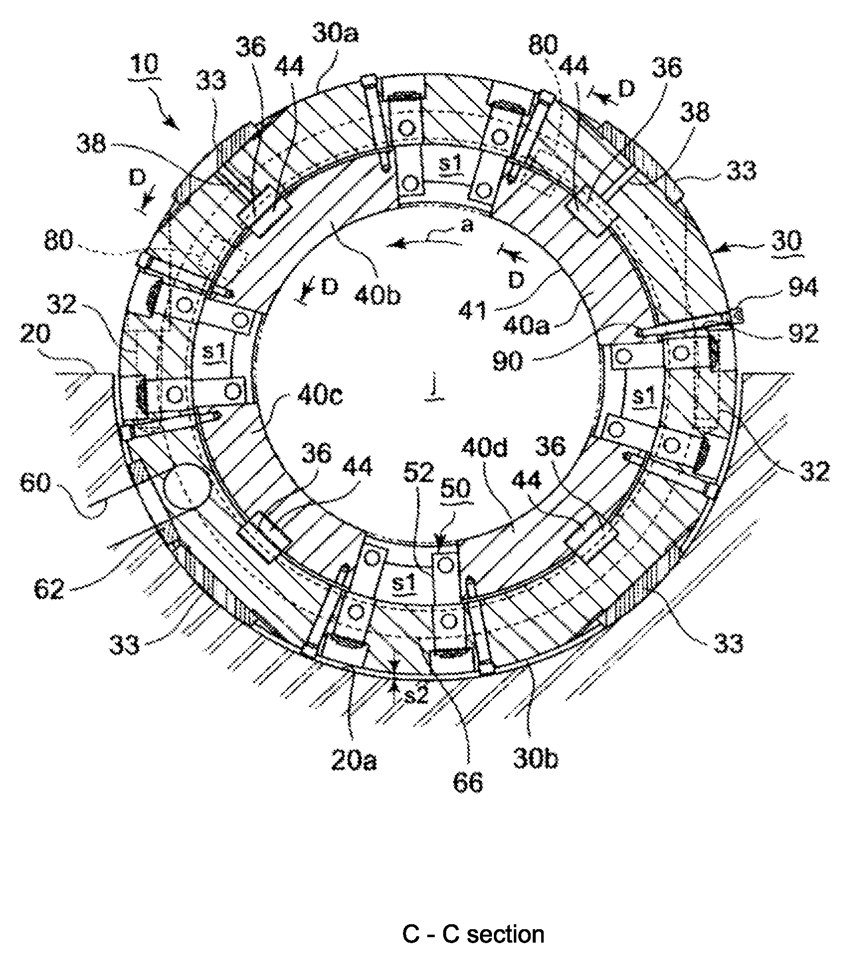
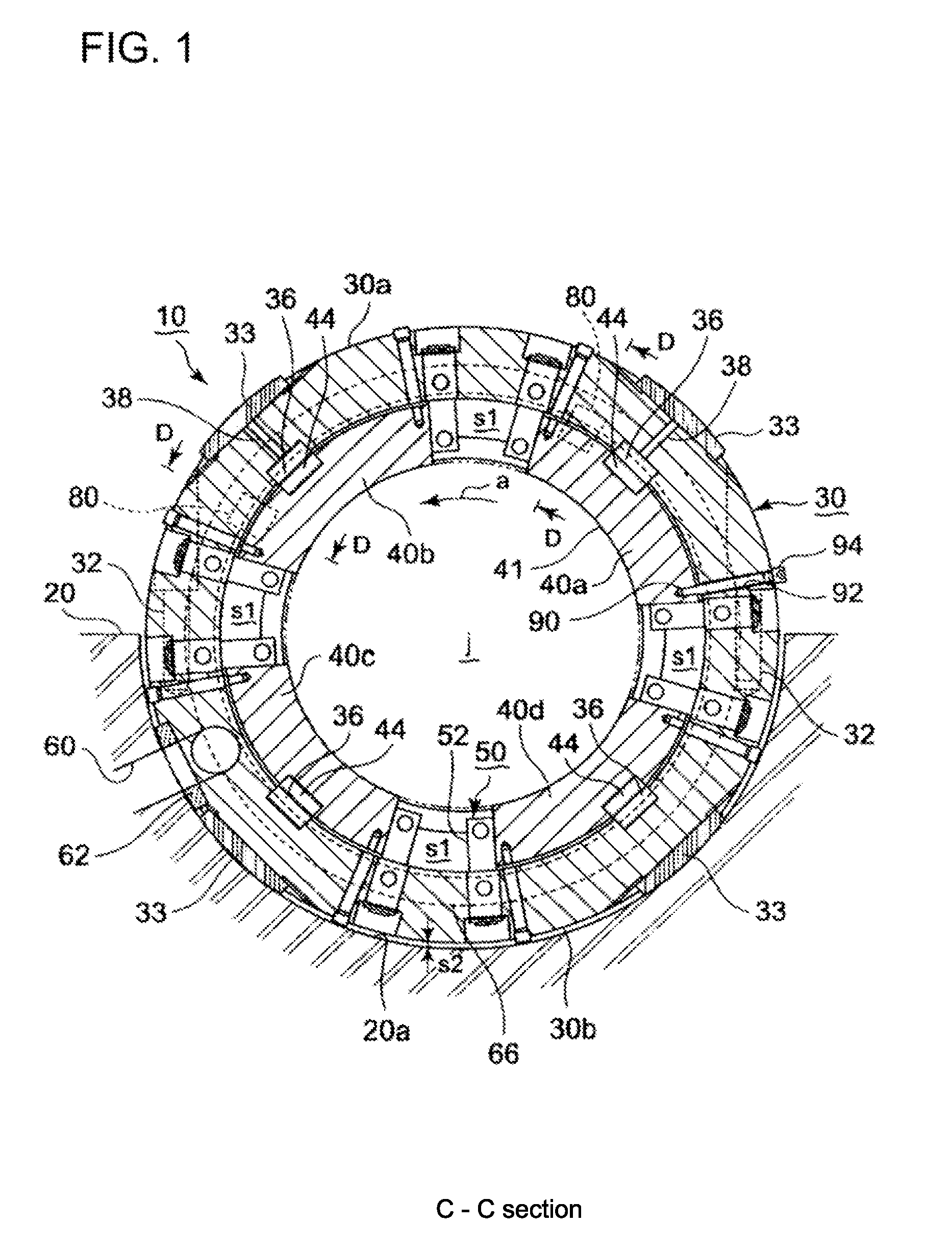
[0068]FIGS. 1 to 3 show an embodiment of the journal bearing of the invention, FIG. 1 is a sectional front view along line C-C in FIG. 2, FIG. 2 is a sectional side view along line B-B in FIG. 3, and FIG. 3 is a rear view viewed in the direction of arrow A in FIG. 2.

[0069]In FIG. 1, a journal j is a rotation shaft of large rotating machine such as a steam turbine, gas turbine, and an electric generator. The diameter of the journal j is as large as about 40 cm, so a journal bearing 10 to support the journal j becomes large in size, and circumferential velocity of the journal j becomes high. The journal j rotates ...


PUM


Abstract

A rotation shaft supporting structure with which the radial clearance between the bearing surface of an upper tilting pad on which self weight of the rotation shaft does not exert and rotating surface of the journal of the rotation shaft can be adjusted so that a high pressure oil film is formed in the clearance and carryover of lubrication oil from an upstream pad to its adjacent downstream pad is prevented.
A plurality of bearing pads (40) are disposed in a bearing housing (30) to surround coaxially a journal j of a rotation shaft, a spring (80) is disposed between the bearing housing (30) and an upper pad (40a, 40b) near downstream side end of the pad in relation to the rotation direction of the journal to push the end part of the pad radially inward, and an oil supply nozzle (50) is mounted to the bearing housing (30) to be located adjacent to the upstream and downstream side end of each pad (40), the upstream side nozzle is to supply lubrication oil to the bearing surface of the pad and the downstream side nozzle is to inject oil toward the journal surface to prevent carryover of lubrication oil from the bearing surface of the upstream pad to that of the downstream pad dragged by the rotating surface of the journal, the nozzles also serving as stoppers to prevent rotational movement of the pad (40).

Description


Claims


Application Information

Patent Timeline
Owner MITSUBISHI HEAVY IND LTD
Why Eureka
Try Eureka