Piercing Terminal, Electric Connector and Their Production Process

Inactive Publication Date: 2010-07-15
HSU CHING JEN
View PDF1 Cites 19 Cited by
  • Summary
  • Abstract
  • Description
  • Claims
  • Application Information

AI Technical Summary

Benefits of technology

[0046]The processing in this invention can not only offset the various problems caused by welding, it has also solved the problems of poor contact and low electric resistance that are unsolvable to the current HDMI electric connector of puncture structure. Meanwhile, it makes it come true that HDMI electric connector with puncture structure has become micro and slimming.
[0047]Another benefit of this invention is that: there are at least two tusks with intertwining tips formed at the electric connection section of the terminals with puncture structure. The tusks are of pyramid shape. The internal sides of the tusks form a cambered surface. The contact area between the tusks and the conductor in the core wires is large, which can reduce the electric resistance. Meanwhile, terminals with this structure are beneficial for the HDMI el

Problems solved by technology

The contact area between the tusk and the conductor in the core wire is ver

Method used


Image

  • Piercing Terminal, Electric Connector and Their Production Process
  • Piercing Terminal, Electric Connector and Their Production Process
  • Piercing Terminal, Electric Connector and Their Production Process

Examples


embodiment 1

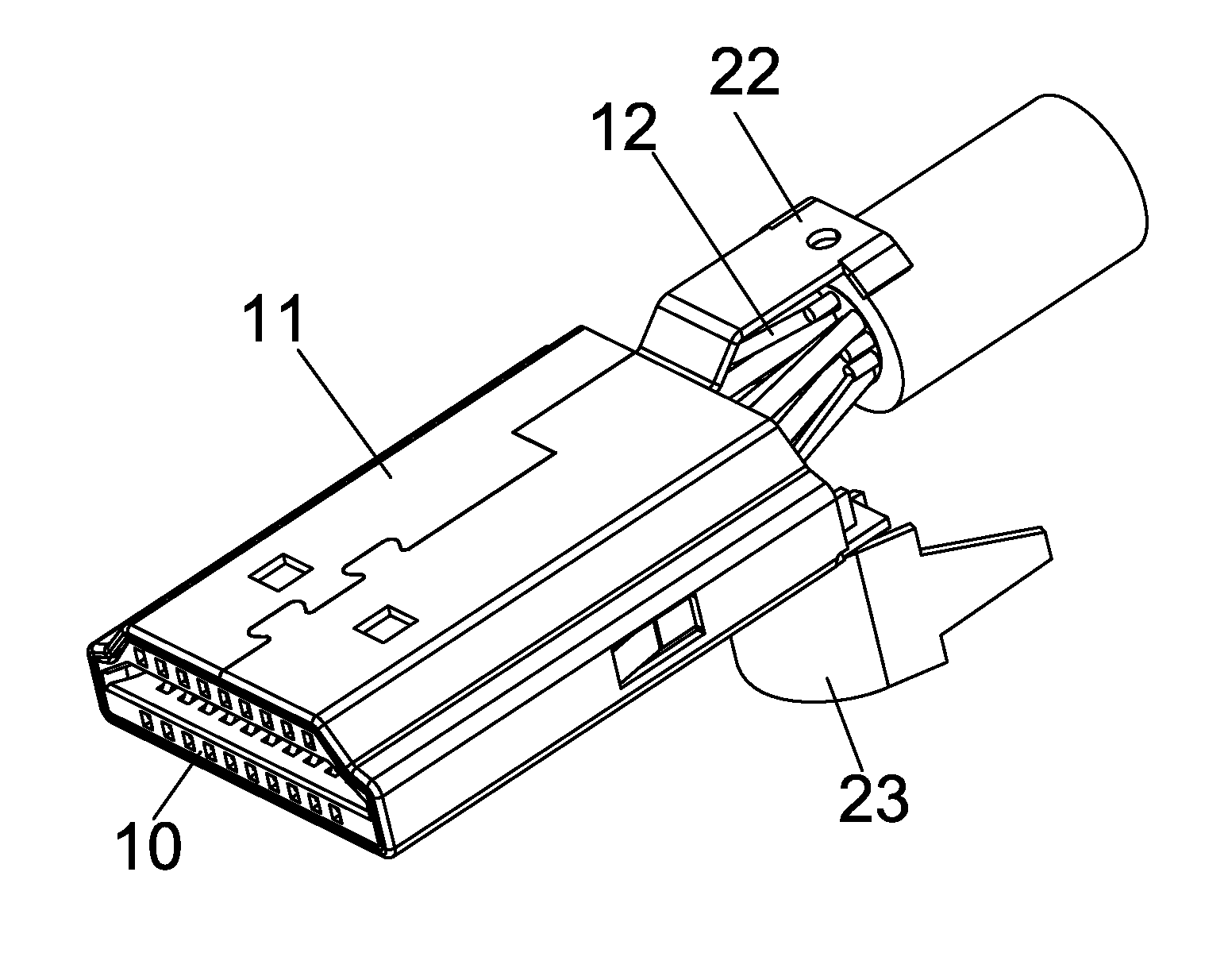
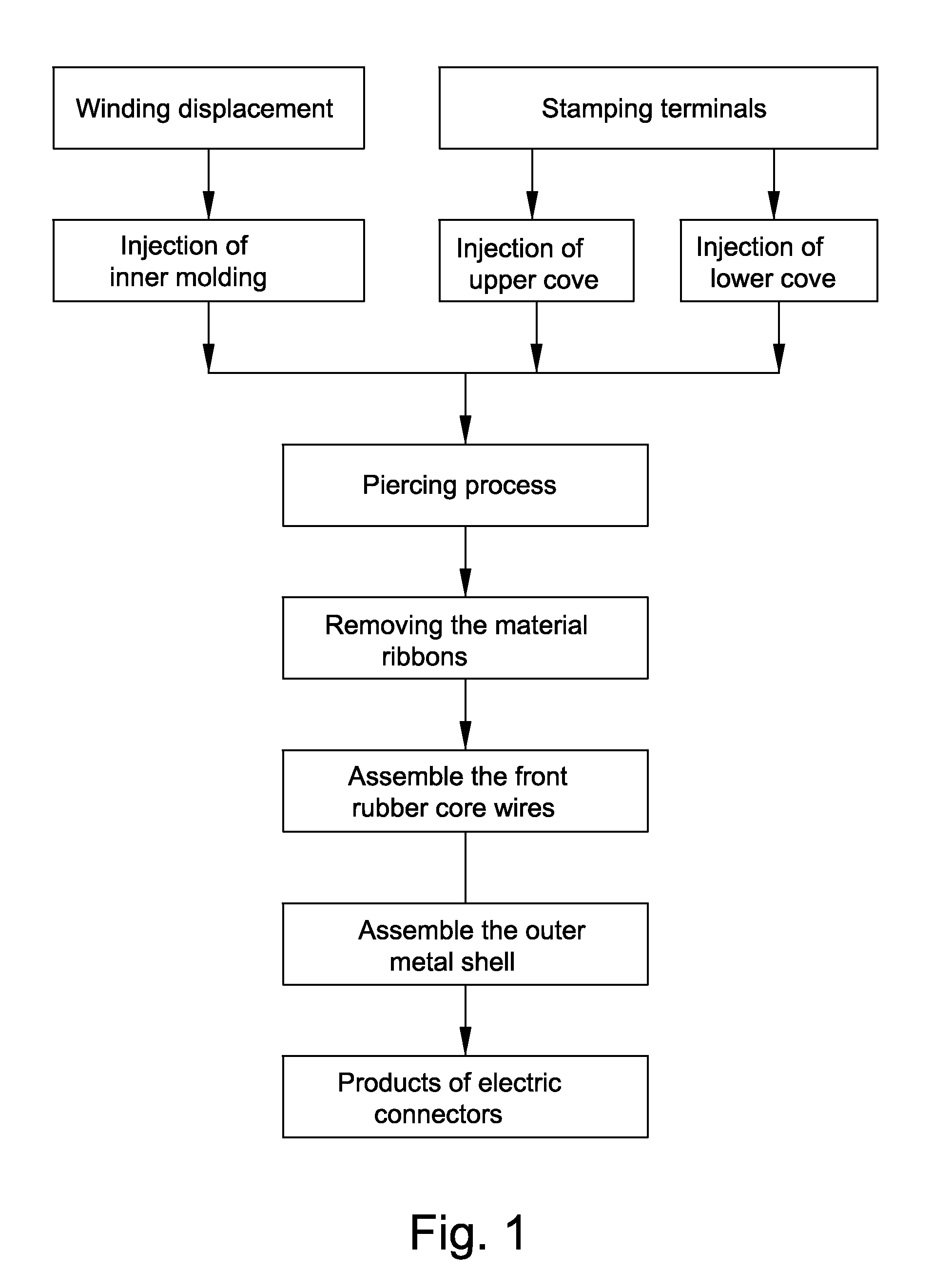
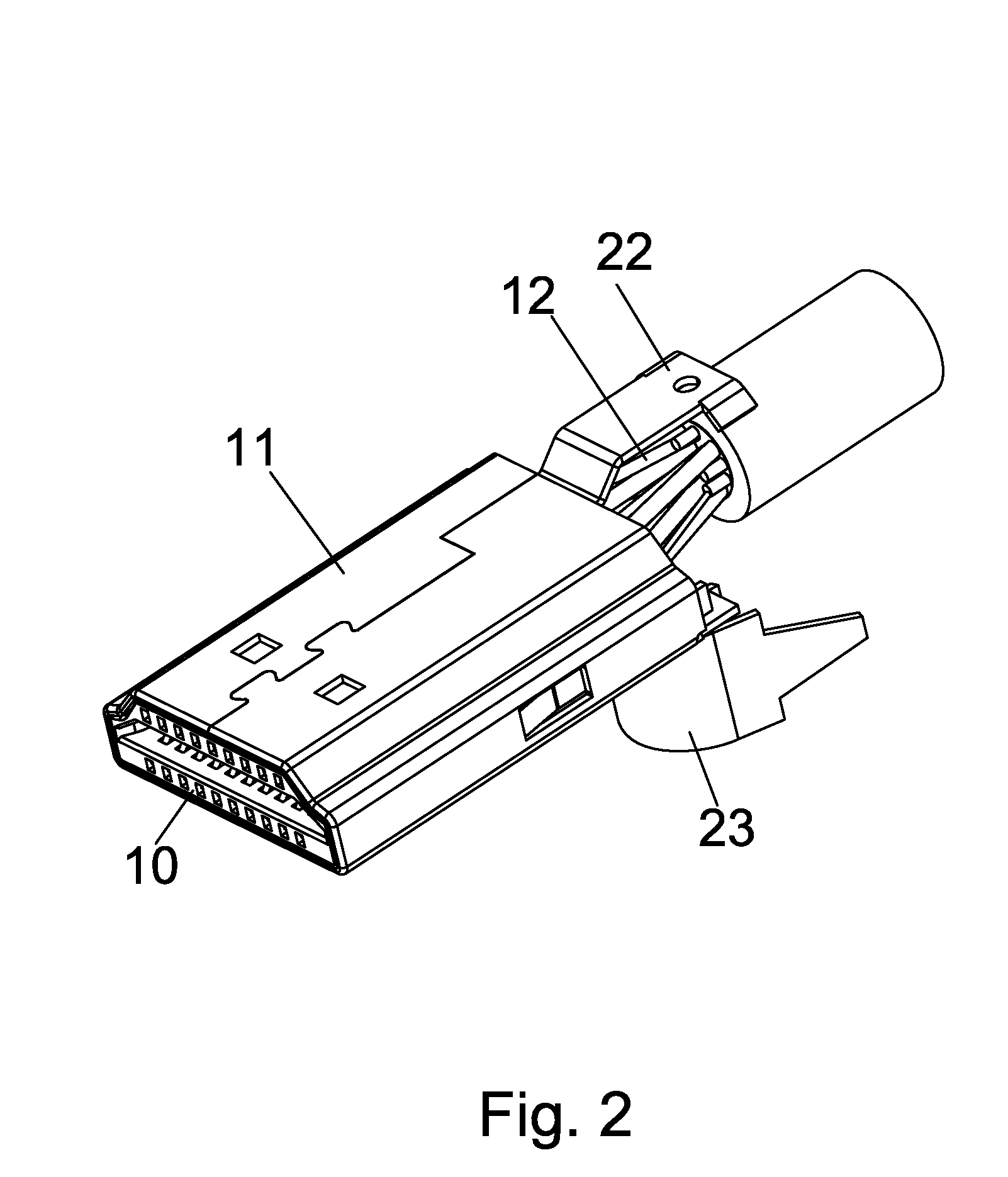
[0075]The processing for the HDMI electric connector with puncture structure, referring to Attached drawing 1, includes the following steps:

[0076]Stamping terminal processing, terminal (13) from stamping molding, as shown in attached drawings 19 to 23. The front of terminal (13) is the electric contact section (1). The middle of terminal (13) is the shaft (2); the rear of terminal (13) is electric contact section (3). There are three tusks (4) with intertwining tips in electric contact section (3). The three tusks (4) are arrayed on the electric contact section (3) of the terminals (13). The tusks (4) from stamping are of pyramid shape. The internal sides (5) of tusks (4) form the cambered surface.

[0077]The internal sides(5) of the tusks(4) located in the front end and the rear end are of the same direction, and are of the opposite direction from internal sides(5) of the tusk(4) located in the middle. The three tusks (4) make a V-shape or U-shape holding frame for the core wires in ...

embodiment 2

[0113]The processing technology of the HDMI electric connector with puncture structure: this embodiment is the continued process after each processing step in embodiment 1 has been completed. Each production step is similar to that in embodiment 1. This embodiment also includes the following steps:

[0114]Injecting of plastic shell: place the outer metal shell (11) and the electric connector combination inside the injection mould and inject a plastic shell outside the outer metal shell (11).

[0115]Since the HDMI electric connector with puncture structure in this invention has made outstanding breakthrough in being micro and slimming, the thickness of the electric connector is far less than the minimum thickness defined by the micro HDMI electric connector. Therefore, it can inject a shell outside the electric connector and the thickness of the electric connector with a shell is still very small. The thickness of the electric connector is far less than the defined size of the micro elec...

embodiment 3

[0117]For the terminals with puncture structure, see the attached drawings 19 to 26. The front end of terminal (13) is the electric contact section (1), the middle of terminal (13) is the shaft (2), and the rear of terminal (13) is the electric contact section (3). There are at least two tusks (4) with intertwining tips formed in electric contact section (3). The tusk (4) is of pyramid shape. The internal side of tusk (4) forms a cambered surface.

[0118]There are three tusks (4) arrayed in electric contact section of terminal (13). The internal sides (5) of the tusks (4) located at the front end and the rear end is of the same direction, while they are of the opposite direction from the internal sides (4) located in the middle. The cambered surface is formed in the upper end of the internal side (5) of the tusk (4).

[0119]The said three tusks (4) form a V-shape or U-shape holding frame for the core wires on the vertical projecting plane. The front of terminal (13) turns 90 degrees aro...


PUM

PropertyMeasurementUnit
Angleaaaaaaaaaa
Structureaaaaaaaaaa
Electrical resistanceaaaaaaaaaa

Abstract

This invention is about the electric connector and its processing technique. More specifically, it involves terminals with puncture structure, electric connector and their processing technique. The processing technique herein includes stamping terminal processing, winding displacement processing, injection upper cover, injecting lower cover, piercing processing, removal of material ribbon, front glue chip assembly, assembly of outer metal shell. Among them, the upper cover and lower cover are injected and molded in the middle and rear of the corresponding terminals in array. The processing technique has tackled the problems as unstable contact, poor contact, high electric resistance and micromation which cannot be solved by the current existing electric connector. There should be at least two tusks whose tips are intertwined molded in the electric connector of piercing terminal. The tusks are the pyramid shape with a cambered surface in the inner side; it reduces the electric resistance of electric connector. The upper and lower covers of piercing HDMI electric connector are respectively molded in the arrayed terminals. The rear end of the terminal has molded piercing tusk. The electric connector has become smaller and lighter, improving its performance in every aspect significantly.

Description

CROSS REFERENCE TO RELATED PATENT APPLICATION[0001]The present application claims the priority of the Chinese patent application No. 200910036628.6 filed on Jan. 14, 2009, which application is incorporated herein by reference.FILED OF THE INVENTION[0002]This invention is about the electric connector and its processing technique; specifically, it touches upon piercing terminal, electric connector and its production process.BACKGROUND OF THE INVENTION[0003]Currently the existing electric connectors include HDMI, DVI, DisplayPort, VGA, Fi-X. Such electric connectors play significant role in electric products. It is responsible for the data transmission and signal sending between electric products, such as the High-Definition Multimedia Interface (HDMI). HDMI can provide transfer rate as much as 10 Gbps and it can transfer high-quality video signals uncompressed and with no need for conversion, suitable for the use in digital appliance such as digital TV, DVD player, DVD broadcaster and...

Claims


Application Information

Patent Timeline
IPC IPC(8): H01R4/24H01R13/02H01R43/00
CPCH01R4/2412H01R9/031H01R43/00Y10T29/4922H01R43/18H01R43/24H01R43/16
Inventor HSU, CHING-JEN
Owner HSU CHING JEN
Why Eureka
Try Eureka