Vehicular air conditioner

a technology of air conditioner and air filter, which is applied in the direction of vehicle heating/cooling devices, vehicle cleaning, vehicle components, etc., can solve the problems of partial reduction of defrost performance, and achieve the effect of reducing defrost performance and good defrost performan

Inactive Publication Date: 2010-07-15
CALSONIC KANSEI CORP
View PDF7 Cites 17 Cited by
  • Summary
  • Abstract
  • Description
  • Claims
  • Application Information

AI Technical Summary

Benefits of technology

[0005]Thus, air discharged from the outlet of the defroster duct can not reach to the lower ends (corresponding to portions P1 in FIG. 7) of the left and right sides of the front window and this partially reduces the defrost performance.
[0006]The present invention is provided based on the described arts and an object of the present invention is to provide a vehicular air conditioner having a good defrost performance for the front window.

Problems solved by technology

Thus, air discharged from the outlet of the defroster duct can not reach to the lower ends (corresponding to portions P1 in FIG. 7) of the left and right sides of the front window and this partially reduces the defrost performance.

Method used


Image

  • Vehicular air conditioner
  • Vehicular air conditioner
  • Vehicular air conditioner

Examples


first embodiment

[First Embodiment

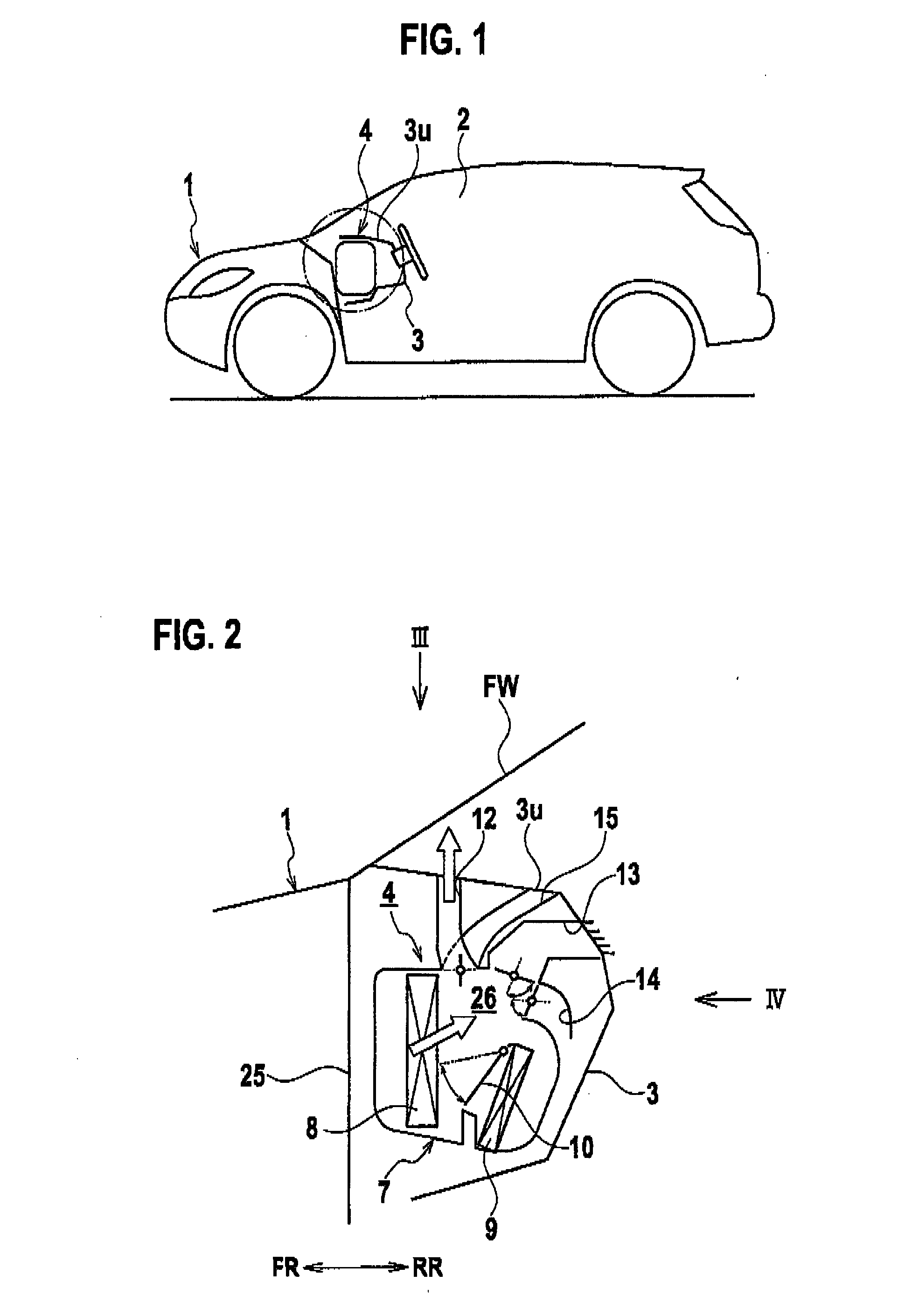
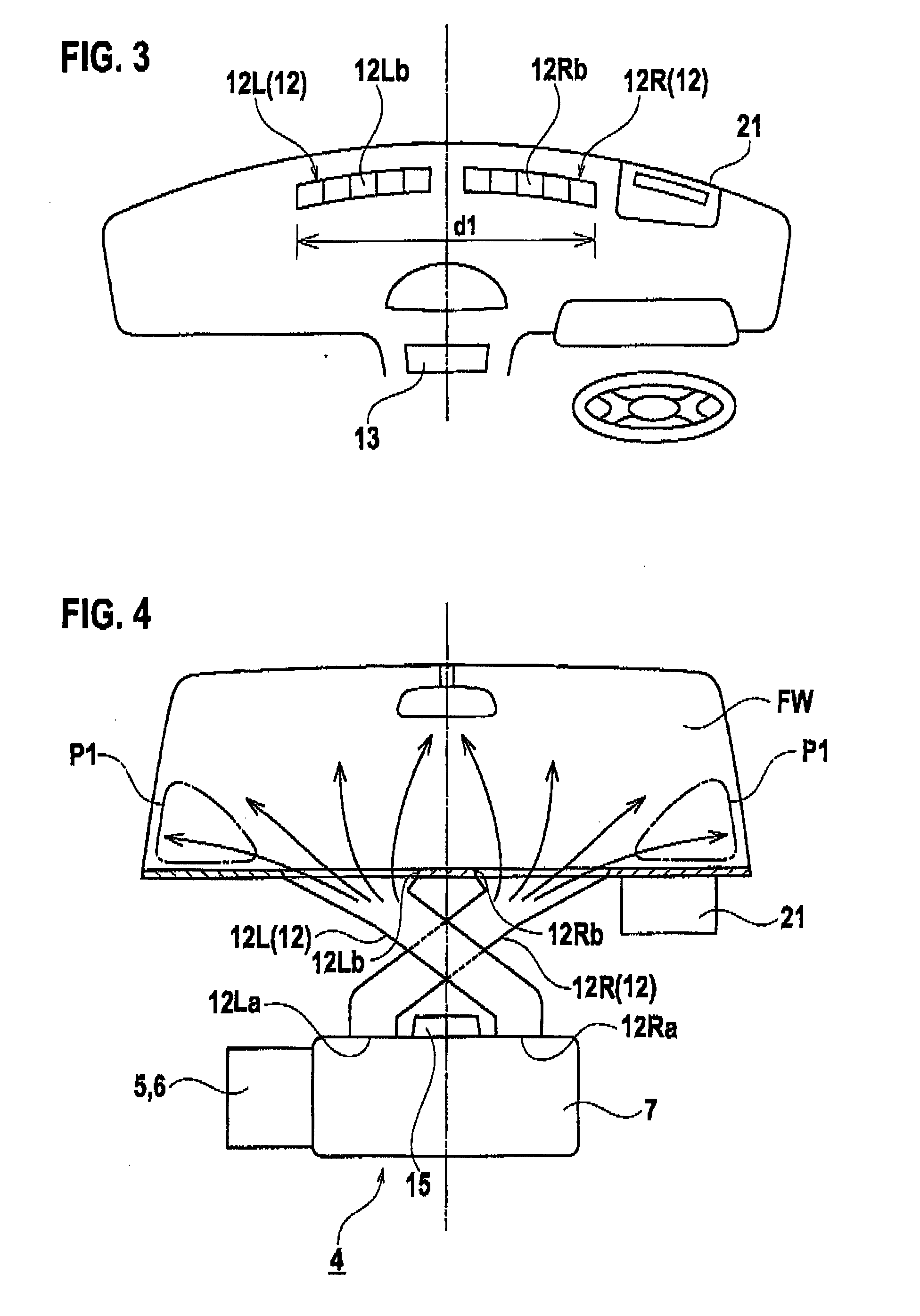
[0017]With reference to FIGS. 1 to 4, a first embodiment of the present invention will be described. FIG. 1 is a diagrammatic view of a vehicle equipped with a vehicular air conditioner according to the first embodiment of the present invention. FIG. 2 is a diagrammatic view of the entire structure of the vehicular air conditioner. FIG. 3 is a top view of an instrument panel, seen along the arrow III in FIG. 2. FIG. 4 is a view seen along the arrow IV in FIG. 2, showing a positional relationship between a defroster duct and a front window.

[0018]As shown in FIGS. 1 and 2, an instrument panel 3 is installed in a front part of a passenger compartment 2 of a vehicle 1. An air conditioning unit 4 is provided in an interior space defined by the instrument panel, that is, a space in front of the instrument panel 3 and in back of a dash panel.

[0019]As shown in FIG. 2, the air conditioning unit 4 includes an intake box 5 (see FIG. 4) formed with an inside air inlet and an ou...

second embodiment

[0033]Next, a second embodiment will be described with reference to FIGS. 5 and 6. In the embodiment described below, the same reference numerals and symbols will be used to designate the same elements as the elements described in the first embodiment, and redundant description for the elements and its effects will be omitted.

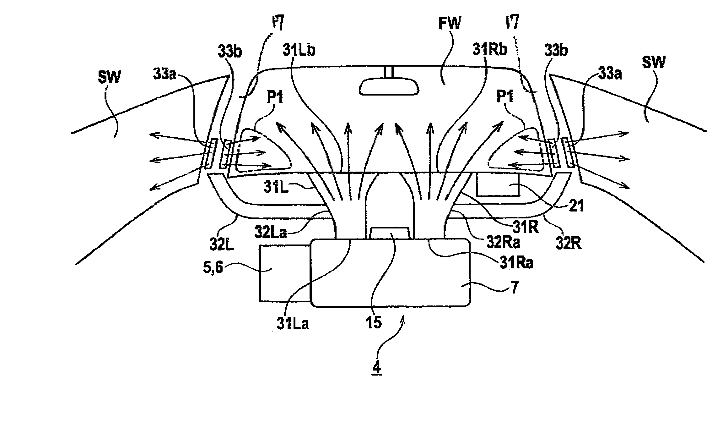
[0034]FIG. 5 is a view of a vehicular air conditioner according to the second embodiment of the present invention, showing a positional relationship between a defroster duct and a front window. FIG. 6 is a view enlarging a driver's seat side portion in the view of FIG. 5.

[0035]In the vehicular air conditioner of the second embodiment, defroster ducts include center defroster ducts 31R, 31L and the side defroster ducts 32R, 32L, and the ducts 31R, 31 L 32R, 32L are arranged without crossing each other, unlike the first embodiment. The other configurations in the second embodiment are similar to those of the first embodiment. The details will be explained.

[0036]A...


PUM


Abstract

Defroster ducts (12R, 12L) includes a right defroster duct (12R) extending from a left side of a temperature control unit (11) toward a right side of a front window (FW) and a left defroster duct (12L) extending from a right side of the temperature control unit (11) toward a left side of the front window (FW). The right and left defroster ducts (12R, 12L) are arranged crossing each other.

Description

TECHNICAL FIELD[0001]The present invention relates to a vehicular air conditioner and, more particularly, to a vehicular air conditioner having a good defrost performance for a front window.BACKGROUND ART[0002]A conventional vehicular air conditioner has a temperature control unit and defroster ducts connected to the temperature control unit in an interior space of an instrument panel provided at the front side of the vehicular passenger compartment (for example, see Japanese Patent Application Laid-Open No. 11-236153).[0003]The defroster ducts are formed with inlets and outlets such that the inlets are connected to the temperature control unit and the outlets are opened through a top wall of the instrument panel. The defroster ducts lead an air flowing from the temperature control unit to discharge toward the inner side of the front window, so as to defog the front window.DISCLOSURE OF THE INVENTION[0004]Recently, vehicular accessories (for example, a head-up display (HUD)) are oft...

Claims


Application Information

Patent Timeline
Patent Type & Authority Applications(United States)
IPC IPC(8): B60S1/54
CPCB60H1/00028B60H2001/00192B60H1/242B60H1/0055
Inventor SANO, MASAHIRO
Owner CALSONIC KANSEI CORP
Why Eureka
Try Eureka