Ultrasonic diagnostic apparatus

Inactive Publication Date: 2010-07-15
HITACHI MEDICAL CORP
View PDF13 Cites 34 Cited by
  • Summary
  • Abstract
  • Description
  • Claims
  • Application Information

AI Technical Summary

Benefits of technology

[0036]In accordance with the present invention, the ultrasonic diagnostic app

Problems solved by technology

However, in the focus setting in conventional ultrasonic diagnostic apparatuses, selective focus positions are not precise, thus the optimal position needs to be determined by switching the focus position several times in the vicinity of the target region.
In the technique disclosed in Patent Document 1, since an operating button is displayed on an image display unit comprising a touch panel and the operator has to use this displayed operating button (soft switch) for setting a focus position, it does not save much trouble over opera

Method used


Image

  • Ultrasonic diagnostic apparatus
  • Ultrasonic diagnostic apparatus
  • Ultrasonic diagnostic apparatus

Examples


first embodiment

1. Configuration of Ultrasonic Diagnostic Apparatus 1

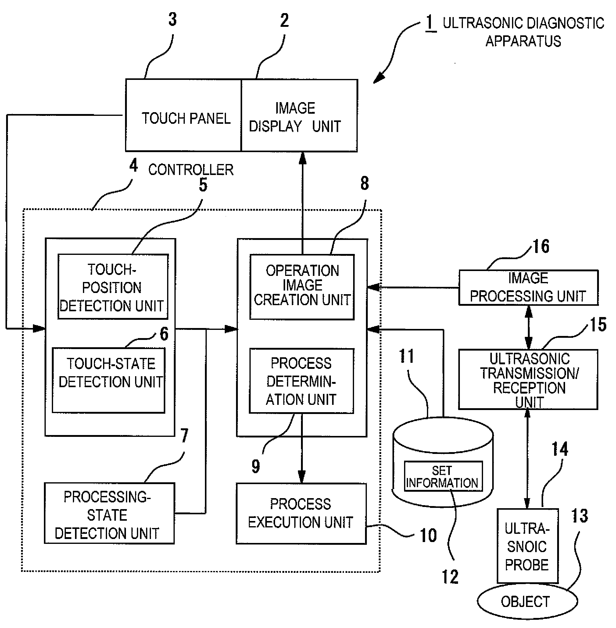
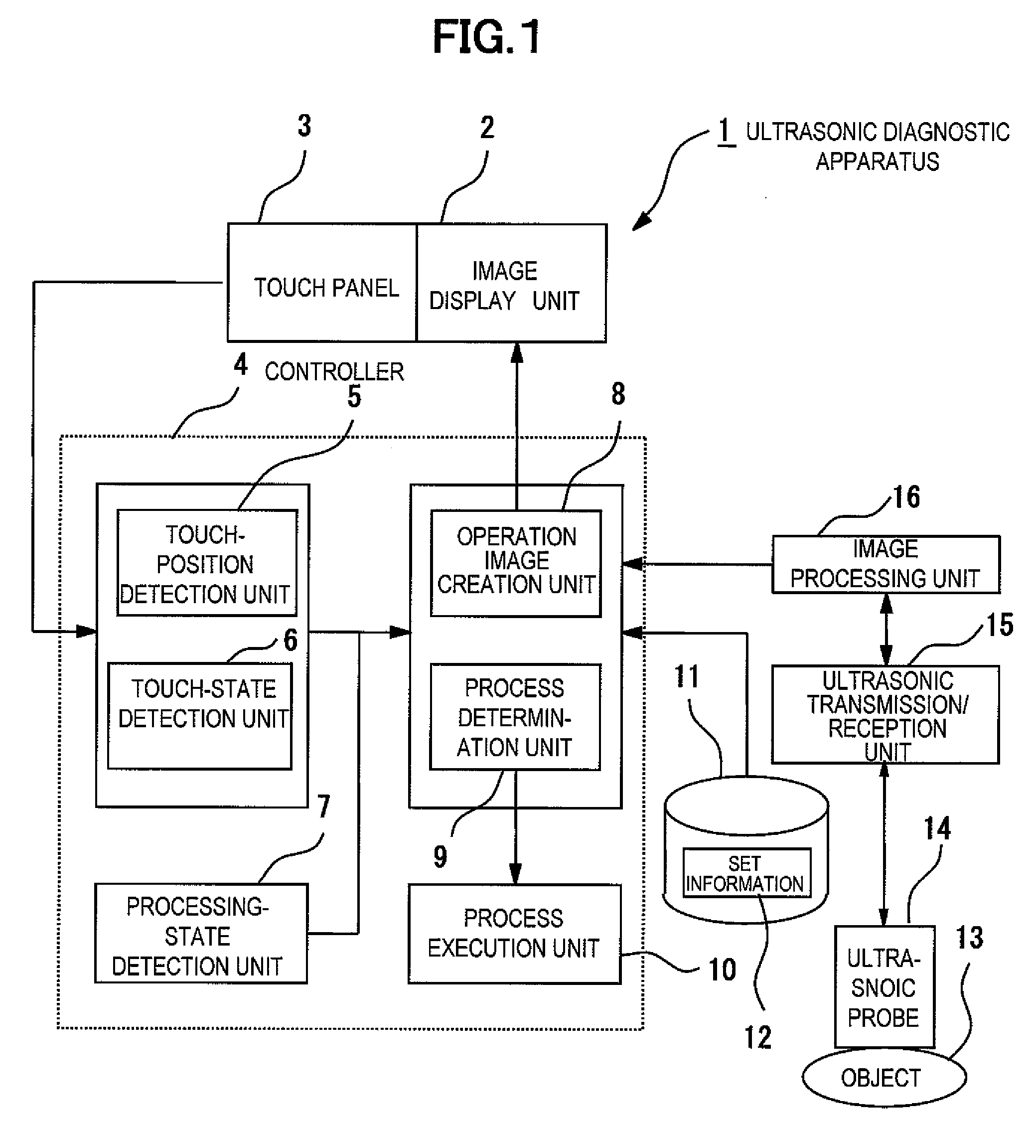
[0064]First, configuration of ultrasonic diagnostic apparatus 1 related to the first embodiment will be described referring to FIG. 1.

[0065]FIG. 1 is a block diagram of ultrasonic diagnostic apparatus 1 related to the first embodiment.

[0066]Ultrasonic diagnostic apparatus 1 comprises ultrasonic probe 14 in which a plurality of transducers for transmitting / receiving ultrasonic waves to / from object 13 is incorporated, ultrasonic transmission / reception unit 15 for transmitting ultrasonic waves by driving ultrasonic probe 14 and processing the received reflected signals, image processing unit 16 for reconstructing the reflected echo signals into ultrasonic images, image display unit 2 for displaying an operation image for supporting operation such as a focus mark or a region of interest frame along with an ultrasonic image, touch panel 3 provided on the anterior surface of image display unit 2, and controller 4 for executing operation...

second embodiment

Configuration of Ultrasonic Diagnostic Apparatus 180

[0129]First, the configuration of ultrasonic diagnostic apparatus 180 related to the second embodiment will be described referring to FIG. 18.

[0130]FIG. 18 is a block diagram of ultrasonic diagnostic apparatus 180 elated to the second embodiment.

[0131]Ultrasonic diagnostic apparatus 180 comprises operation monitor 181 and observation monitor 182 for displaying an operation image for supporting operation such as a focus mark or a region of interest frame along with an ultrasonic image.

[0132]While touch panel 3 of ultrasonic diagnostic apparatus in FIG. 1 is provided on image display unit 2, ultrasonic diagnostic apparatus 180 in FIG. 18 comprises operation monitor 181 separate from observation monitor 182, and touch panel 183 is provided on this operation monitor 181. Controller 4, storage unit 11, setting information 12, image processing unit 16, ultrasonic transmission / reception unit 15, and ultrasonic probe 14 in FIG. 18 are the ...


PUM


Abstract

Provided is an ultrasonic diagnostic apparatus which can improve operability and diagnosis efficiency.
An ultrasonic diagnostic apparatus (1) includes: an ultrasonic probe (14) which transmits/receives an ultrasonic wave to/from an object (13) to be examined; an image processing unit (16) which configures an ultrasonic image according to the ultrasonic reception signal outputted from the ultrasonic probe (14); an image display unit (2) which displays the configured ultrasonic image; a touch panel (3) arranged on the front face of the image display unit (2); a touch position detection unit (5) which detects a touch position on the touch panel (3); a touch state detection unit (6) which detects a touch state on the touch panel; a processing state detection unit (7) which detects the current processing state; and a process decision unit (9) which decides a process to be executed according to at least one of the detected touch position, touch state, and the processing state and executes the process.

Description

TECHNICAL FIELD[0001]The present invention relates to an ultrasonic diagnostic apparatus for imaging and displaying ultrasonic images, particularly the ultrasonic diagnostic apparatus comprising a touch panel for operation.BACKGROUND ART[0002]In conventional ultrasonic diagnostic apparatuses, an operator sets a focus position by operating a focus position switch for exclusive purpose. The operator sets the focus position to be at the nearest position to a diagnostic target portion while referring to an ultrasonic image and a focus mark to be displayed on the side thereof.[0003]Also, the ultrasonic diagnostic apparatus has been proposed that displays an operation button on an image display unit on which a touch panel is placed (For example, refer to [Patent Document 1]).[0004]Patent Document 1: JP-A-2006-26256DISCLOSURE OF THE INVENTIONProblems to be Solved[0005]However, in the focus setting in conventional ultrasonic diagnostic apparatuses, selective focus positions are not precise,...

Claims


Application Information

Patent Timeline
IPC IPC(8): A61B8/14
CPCA61B8/00A61B8/469A61B8/467A61B8/465A61B8/4427A61B8/463
Inventor YAMAMOTO, MASA
Owner HITACHI MEDICAL CORP
Why Eureka
Try Eureka