Mixed light source device and light emitting control method thereof, and projection system

A technology of mixed light source and luminous control, applied in the field of projection, can solve the problem of no infrared image display, etc., and achieve the effect of a wide range of applications

Active Publication Date: 2017-02-01
APPOTRONICS CORP LTD
View PDF11 Cites 5 Cited by
  • Summary
  • Abstract
  • Description
  • Claims
  • Application Information

AI Technical Summary

Problems solved by technology

[0003] For the infrared light region with a wavelength above 780nm invisible to the human eye, it is mainly produced in the night environment. In this environment, there are some requirements for the visibility of infrared light, such as in military operations, but the existing projection system has not yet Technology for displaying infrared images

Method used


Image

  • Mixed light source device and light emitting control method thereof, and projection system
  • Mixed light source device and light emitting control method thereof, and projection system
  • Mixed light source device and light emitting control method thereof, and projection system

Examples


Embodiment 1

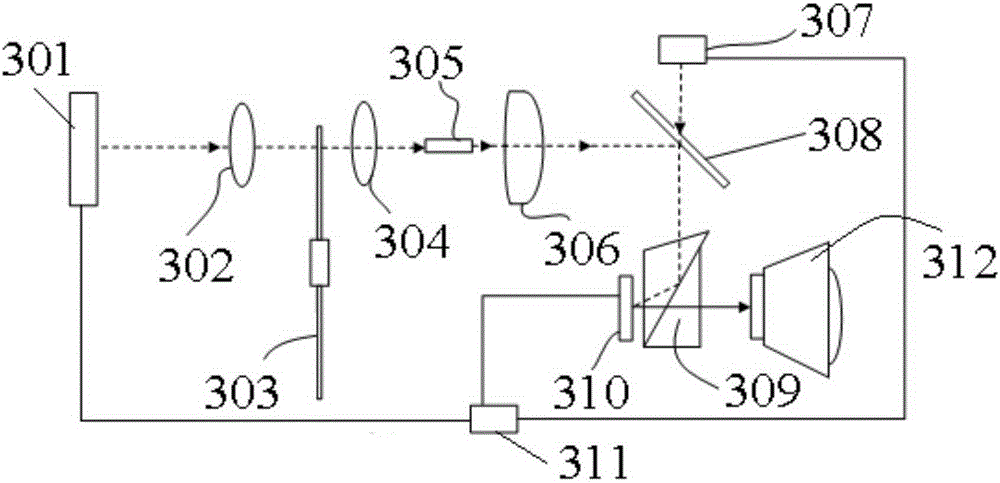
[0038] Such as figure 1 Shown is the projection system of this embodiment, including the system including a main light source 301, a first collection lens 302, a color wheel 303, a second collection lens 304, a square rod 305, a relay system 306, an infrared light source 307, and a dichroic film 308 , a TIR (Total Internal Reflection) prism 309 , a DMD (Digital Mirror Device, Digital Micromirror Device) 310 , a controller 311 and a projection lens 312 .

[0039] The main light source 301, the first collecting lens 302, the color wheel 303, the infrared light source 307, and the controller 311 together constitute the mixed light source device of the system.

[0040] The main light source 301 is a 445nm blue laser for emitting blue laser light as excitation light, and 307 is an 800nm ​​IR (infrared, infrared) laser.

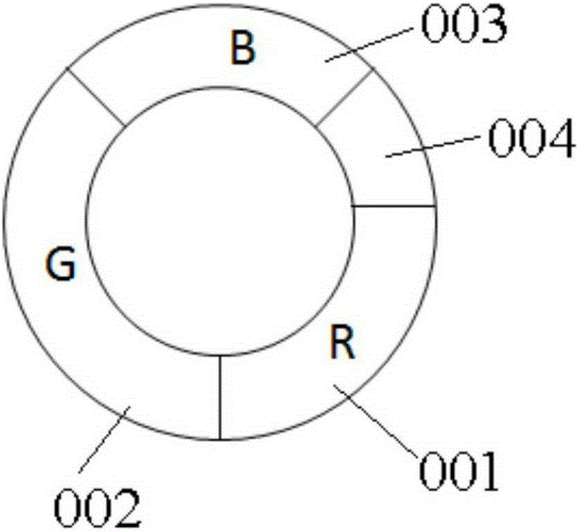
[0041] The color wheel 303 is used as the color light generating device of the mixed light source device, and its structure is as follows: figure 2 As shown, it...

Embodiment 2

[0058] Such as Figure 5As shown, the projection system of this embodiment includes a main light source 405, a spectroscopic filter 406, a color wheel 408, a driving device 409, a shaping lens 410, a prism device 411, a spatial light modulator (Spatial LightModulators, SLM) 412, and a projection lens 415 , a controller 413 , an infrared light source 414 , and a reflector 407 . Wherein, the main light source 405, the spectral filter 406, the infrared light source 414, the reflector 407, the color wheel 408, the driving device 409, and the controller 403 together constitute the light emitting device of the projection device.

[0059] The main light source 405 is used to emit blue laser light, and the spectral filter 406 is used to project blue laser light and reflect infrared light.

[0060] The structure of the color wheel 408 is as follows Image 6 As shown, it includes the red color segment area 001, the green light segment area 002, the blue light segment area 003 and the ...

Embodiment 3

[0066] Such as Figure 7 As shown, the structure of the projection system of this embodiment differs from that of Embodiment 2 in that there is only one main light source 405 instead of an infrared light source separately, and the main light source 405 emits excitation light; the color wheel 408 refers to Image 6 structure design, but the material coated with the infrared color segment 005 of the color wheel 408 generates infrared light when it receives excitation light, therefore, the RGBIR light sequence can be generated from the color wheel, and it does not necessarily require the controller 413 to control the main The light source 405 is turned on and off, and the controller 413 controls the spatial light modulator 412 in the same manner as the first and second embodiments.


PUM


Abstract

The invention discloses a mixed light source device and a light emitting control method thereof, and a projection system. The mixed light source device is composed of a main light source emitting exciting light, an infrared light source emitting infrared light, a color wheel, and a controller. The color wheel generates tri-visible light under irradiation of exciting light. The controller connected with the main light source and the infrared light source is used for outputting a visible light control signal and an infrared light control signal and controlling the mixed light source device to emit a tri-visible light and infrared light alternately by controlling turning-on and turning-off states of the main light source and the infrared light source. An optical modulator of the projection system modulates the tri-visible light according to a visible light image signal; and the infrared light is modulated based on an infrared light image signal. According to the invention, because of alternate emission of tri-visible light and infrared light, a visible projection image and an infrared projection image are formed on a same screen, so that the display function is extended and thus the product has high competitiveness and a wider application range.

Description

technical field [0001] The invention relates to the field of projection technology, in particular to a mixed light source device, a lighting control method thereof, and a projection system. Background technique [0002] At present, spatial light modulators are widely used in the field of projection display. Spatial light modulators generally include LCD (Liquid Crystal Display, liquid crystal display), LCOS (Liquid Crystal on Silicon, liquid crystal with silicon, also known as liquid crystal on silicon), DMD (Digital Mirror Device, Digital Micromirror Device, digital micromirror device), etc., the single-chip spatial light modulator projection system realizes color projection display based on time-sequentially switched visible light. widely used in the market. In terms of light sources for projection systems, semiconductor lasers excite different fluorescent pink segments on the color wheel to form different visible lights. This method has the advantages of high light effic...

Claims


Application Information

Patent Timeline
Patent Type & Authority Applications(China)
IPC IPC(8): G03B21/20
Inventor 郭祖强胡飞侯海雄李屹
Owner APPOTRONICS CORP LTD
Why Eureka
Try Eureka