Dynamic Pressure Gauged Breast Pump

a pressure gauged, breast pump technology, applied in the field of breast pumps, can solve the problems of negative pressure pulling and breast deformation, and achieve the effect of reducing the risk of breast deformation

Inactive Publication Date: 2010-07-15
WESTON RICHARD SCOTT
View PDF12 Cites 13 Cited by
  • Summary
  • Abstract
  • Description
  • Claims
  • Application Information

AI Technical Summary

Benefits of technology

[0007]In the present system, a pump is connected in fluid communication to the recess of the breast shield. As a result of this connection, the pump is able to cyclically apply a negative pressure to the recess. Importantly, a pressure gauge positioned in the fluid line between the pump and the recess of the breast shield. Due to this structure, the gauge can monitor a dynamic operational pressure on the breast while expressing milk from the breast. Further, the system includes a display mec

Problems solved by technology

Further, the negative pressure may

Method used


Image

  • Dynamic Pressure Gauged Breast Pump
  • Dynamic Pressure Gauged Breast Pump
  • Dynamic Pressure Gauged Breast Pump

Examples


Embodiment Construction

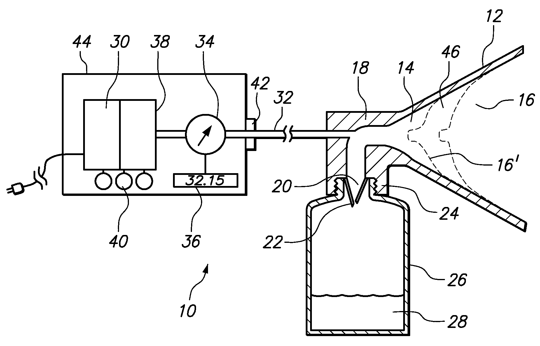
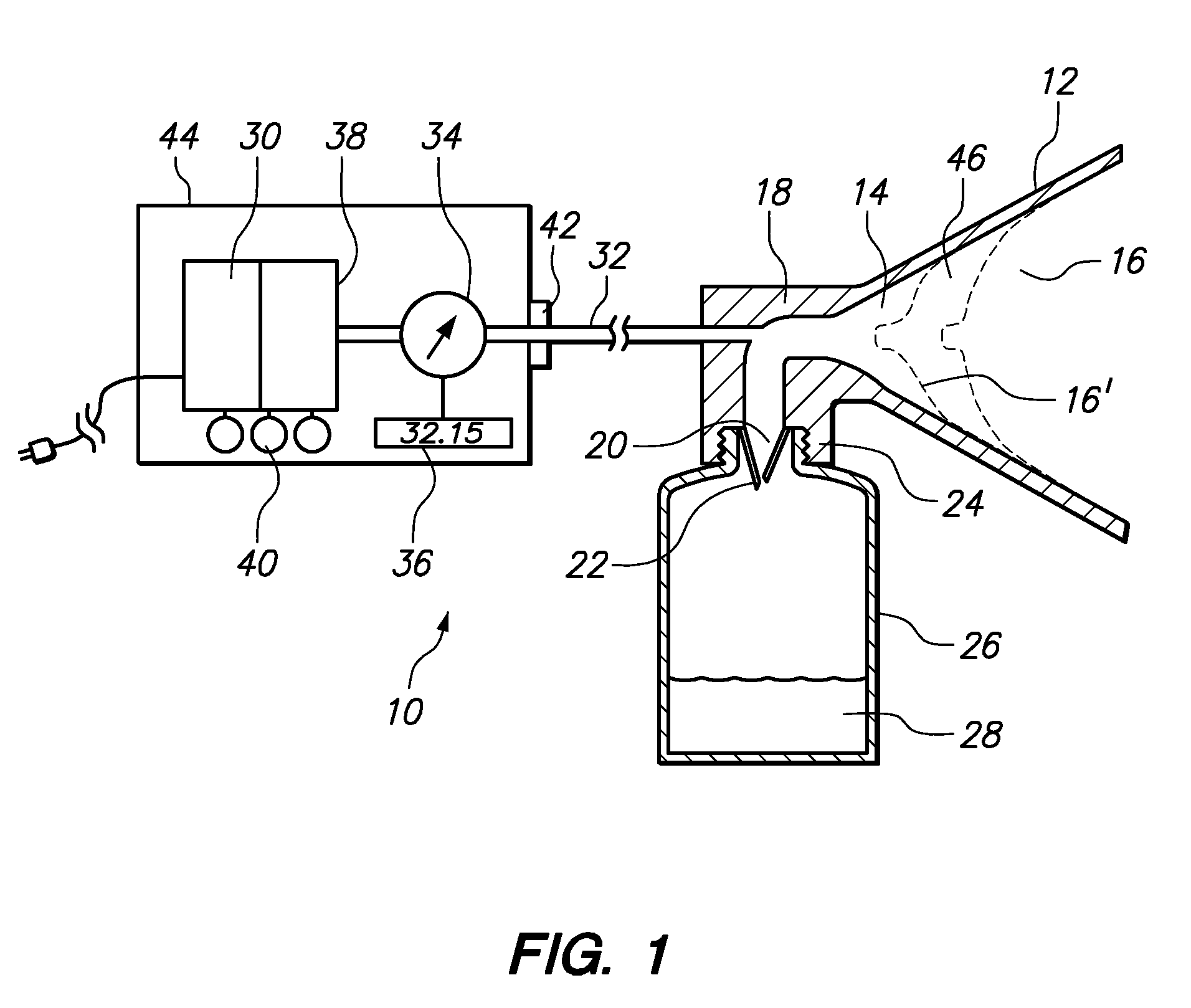
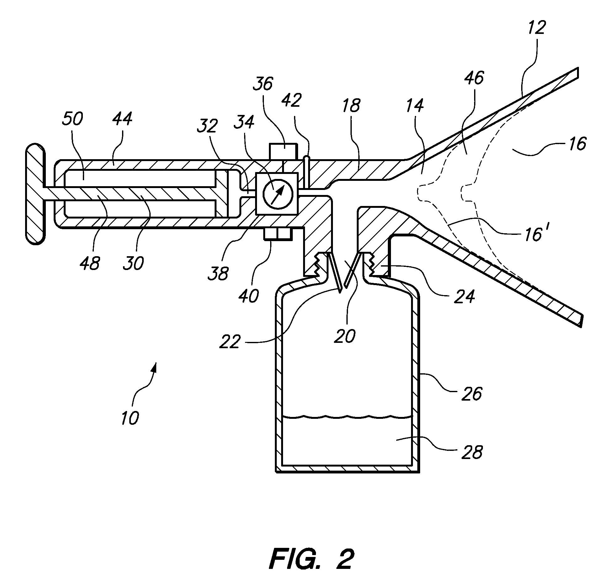
[0012]Referring initially to FIG. 1, a dynamic pressure gauged breast pump system is shown and generally designated 10. In FIG. 1, the system 10 includes a breast shield 12 that defines a recess 14 for receiving a breast 16. As shown, the breast shield 12 is formed by a housing 18. Structurally, the housing 18 forms an outlet 20 in fluid communication with the recess 14. Also, a one-way valve 22 is positioned in the outlet 20. As shown, the housing 18 further includes an adaptor portion 24 that selectively engages the outlet 20 to a collection reservoir 26 for receiving milk 28. Though exemplary, in FIG. 1 such engagement is attained via threaded connection.

[0013]Still referring to FIG. 1, the system 10 also includes an automatic pump 30 for cyclically applying a negative pressure to the recess 14. As shown, the pump 30 is powered by battery or through connection to an electrical supply via a cord and plug to create cyclically varying negative pressure. Further, the pump 30 is conne...


PUM


Abstract

A breast pump system is disclosed for cyclically applying and simultaneously monitoring the negative pressure imposed while expressing milk from a breast. Structurally, the system includes a breast shield formed with a recess for receiving a breast. Further, a collection reservoir is connected to the recess of the breast shield for receiving milk therefrom. A pump is connected in fluid communication to the recess of the breast shield for applying the negative pressure to the breast. Also, a one-way valve is positioned between the recess and the collection reservoir to permit flow of milk into the collection reservoir while preserving ambient pressure in the collection reservoir. Importantly, a pressure gauge is connected between the pump and the breast shield for monitoring the operational pressure on the breast in real time. Further, a regulator manages the negative pressure applied by the pump in response to the monitored operational pressure.

Description

FIELD OF THE INVENTION[0001]The present invention pertains generally to breast pumps. More particularly, the present invention pertains to systems and methods for monitoring pressures imposed by negative pressure breast pumps in real time. The present invention is particularly, but not exclusively, useful as a breast pump system that displays the operational pressure imposed on the breast while milk is expressed from the breast.BACKGROUND OF THE INVENTION[0002]For various reasons, a lactating woman may desire to express and collect her milk. Accordingly, breast pumps have long been provided. Typically, breast pumps are used to allow a nursing mother to express beast milk to feed to her child at a later time when the mother may be absent. In other cases, the child is unable to nurse from the breast and may be fed breast milk by bottle. Also, a mother may have difficulties related to excessive breast milk production and require milk to be expressed despite normal nursing by her child....

Claims


Application Information

Patent Timeline
IPC IPC(8): A61M1/06
CPCA61M1/0031A61M1/0027A61M1/06A61M1/732A61M1/74
Inventor WESTON, RICHARD SCOTT
Owner WESTON RICHARD SCOTT
Why Eureka
Try Eureka