Non-contact handling device

A handling device, non-contact technology, applied in the field of non-contact handling devices, to achieve the effect of large suspension force

Active Publication Date: 2011-06-22
杭州孚亚科技有限公司
View PDF9 Cites 12 Cited by
  • Summary
  • Abstract
  • Description
  • Claims
  • Application Information

AI Technical Summary

Problems solved by technology

[0010] The technical problem to be solved by the present invention is to provide a non-contact handling device with low energy consumption and high suspension force, so as to solve the problems of low suspension force, high energy consumption, high cost, small scope of application and movement problems in the above-mentioned existing patent application for the invention. Technical problems such as limited range

Method used


Image

  • Non-contact handling device
  • Non-contact handling device
  • Non-contact handling device

Examples


Embodiment 1

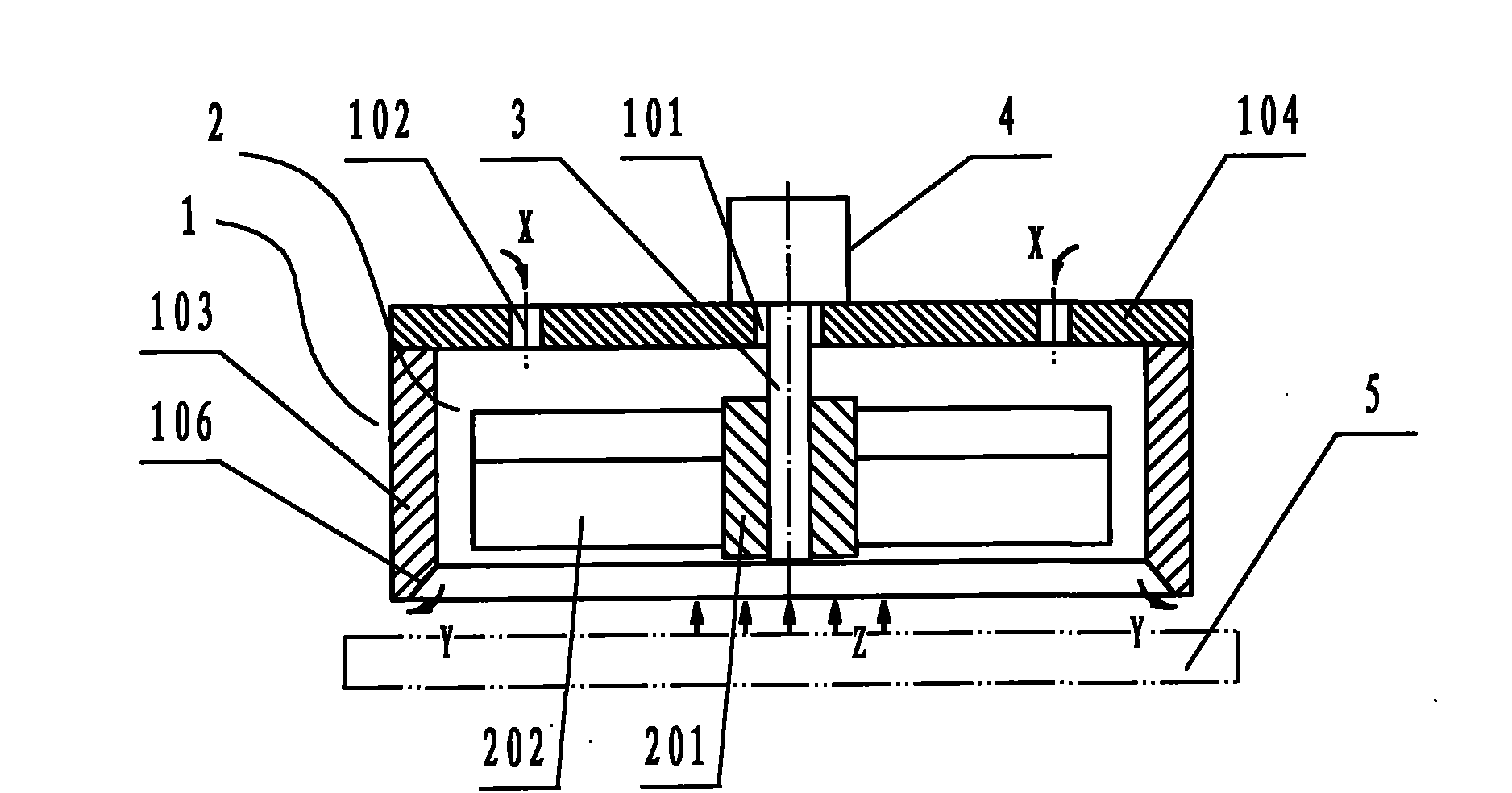
[0038] Figure 1 ~ Figure 2 Disclosed in is a non-contact conveying device, which includes a cover body 1 with a cylindrical inner hole, a revolving fan blade 2 located in the cover body 1, and a power input shaft 3 that drives the revolving fan blade to rotate; The cover body 1 is a split type cover body. The split type cover body is composed of a cover body 103 with open ends and a cylindrical inner hole and an upper cover plate 104 located at the top of the cover body. The outer side of the cover body is a cylindrical structure. The center of the upper cover plate 104 is provided with a power input shaft installation hole 101 and suction ports 102 distributed around the power input shaft installation hole, and a square chamfer 106 is provided on the inside of the lowermost end of the cylindrical body 103; 2. It consists of a shaft sleeve 201 and blades 202 evenly distributed on the shaft sleeve. The lower part of the blade 202 is vertical and the upper part is curved. There...

Embodiment 2

[0040] Figure 4 Disclosed in is another kind of non-contact conveying device, same as the first embodiment, the device includes a cover body 1 with a cylindrical inner hole, a revolving fan blade 2 located in the cover body 1, and drives the revolving fan blade to rotate The power input shaft 3; the difference is: the cover body 1 is an integral type cover body, the top of the integral type cover body and the cover body with a cylindrical inner hole are connected as a whole, the described The power input shaft installation hole 101 and the suction ports 102 distributed around the power input shaft installation hole are arranged on the top of the cover body; the inside of the lowermost end of the cover body 1 is provided with a circular chamfer 106; There is a bend transition between the vertical part and the curved part (see Figure 5 ). Its specific structure is as follows:

[0041] A non-contact conveying device, which includes a cover body 1 with a cylindrical inner hol...

Embodiment 3

[0043] Image 6 Disclosed in is another non-contact conveying device, which is the same as the first embodiment. The device includes a cover body 1 with a cylindrical inner hole, a revolving fan blade 2 located in the cover body 1, and drives the revolving fan blade to rotate. The power input shaft 3, and the cover body 1 is a split type cover body; the difference is: the outer periphery of the bottom of the cover body 1 is also provided with an annular platform 105, so as to facilitate the installation of the cover body and play the role of a buffer The effect is to ensure that the workpiece does not collide with the device, because a thin air layer is sandwiched between the annular platform 105 and the workpiece 5, and this air layer has the effect of absorbing vibration.


PUM


Abstract

The invention discloses a non-contact handling device and relates to a handling device. The device comprises a cover body with a cylindrical inner hole, gyratory fan blades arranged in the cover body and a power input shaft for driving the gyratory fan blades to rotate, wherein the central position of the top end of the cover body is provided with a power input shaft mounting hole and air sucking ports distributed on the periphery of the power input shaft mounting hole; each gyratory fan blade consists of a shaft sleeve and blades distributed on the shaft sleeve; the lower parts of the blades are vertical, the upper parts are bent, and the bending directions of the blades are consistent with the rotation directions of the gyratory fan blades; and one end of the power input shaft passes through the power input shaft mounting hole and is connected with the shaft sleeve of the gyratory fan blades in the cover body, while the other end is connected with a rotary drive device arranged outside the cover body. The device has the characteristics of low energy consumption and strong suspension force, can be driven by adopting a motor, has the advantages of low cost, wide application range, large motion range, and the like, conforms to the development trends of energy saving and high efficiency in the semiconductor industry at present and is easy to popularize and apply.

Description

【Technical field】: [0001] The invention relates to a conveying device, in particular to a non-contact conveying device for conveying a workpiece with a flat surface without any contact with the workpiece. 【Background technique】: [0002] With the rapid development of electronic technology, semiconductor silicon crystal panels tend to be highly integrated and large-scale substrates. At the same time, high-performance devices such as liquid crystal glass panels are also developing in the direction of large-scale. When handling these devices, there must be no contact, because contact can cause scratches and static electricity on the surface of the device, resulting in waste. In addition, in the aspect of pharmaceutical production, in the process of drug handling, drug contamination often occurs due to contact. Therefore, the demand for non-contact handling has been increasing. In order to avoid problems caused by contact during transportation, non-contact transportation device...

Claims


Application Information

Patent Timeline
Patent Type & Authority Applications(China)
IPC IPC(8): B25J15/06
Inventor 黎科
Owner 杭州孚亚科技有限公司
Why Eureka
Try Eureka