Ultrahigh-pressure cyclone desanding and separating device

A cyclone desanding and separation device technology, which is applied in the direction of separation methods, sedimentation separation, and sediment separation by centrifugal force, can solve the problems of complex fluid components in wells, heavy workload of filter cartridges, and low efficiency of sand separation. Remarkable sand removal effect and improved work efficiency

CN113521814APending Publication Date: 2021-10-22SUZHOU DOUSON DRILLING & PRODION EQUIP
7 Cites 1 Cited by

Patent Information

Authority / Receiving Office
CN · China
Patent Type
Applications(China)
Current Assignee / Owner
Publication Date
2021-10-22

Smart Images

  • Figure 1
    Figure 1
  • Figure 2
    Figure 2
  • Figure 3
    Figure 3
Patent Text Reader

Abstract

The invention discloses an ultrahigh-pressure cyclone desanding and separating device which comprises a core shaft, wherein a baffle is welded on the outer surface of the core shaft; a conical cylinder which is fixedly arranged at one end of the core shaft in a sleeving manner, and a lining is embedded in the inner wall of the conical cylinder; and a flow channel which is used for removing sand and is formed in the core shaft. According to the technical key points, when liquid enters the conical cylinder, the tangential speed can be obtained through the fluid liquid inlet, and solid is automatically separated from gas through the rotational flow effect of the conical cylinder, wherein the solid can be deposited to the lower portion, and then the liquid is discharged from the fluid liquid outlet, so that automatic separation of the liquid, the solid and the gas is achieved; solids such as sand obtained through separation are discharged from the bottom of the conical cylinder, and separated gas and liquid are discharged from the upper part of the core shaft; when rotational flow is generated, as the upper part of the device is cylindrical and the lower part of the device is conical, fluid passes through the inner surface of the cylinder and then reaches the inner surface of the cone, and the fluid can realize high-speed rotation, so that the working efficiency is improved while the sand removal effect is remarkable.
Need to check novelty before this filing date? Find Prior Art

Description

technical field

[0001] The invention belongs to the technical field of sand removal and separation, in particular to an ultra-high pressure cyclone sand removal and separation device. Background technique

[0002] During the fracturing process of oil and natural gas, especially in the process of increasing production of unconventional oil and gas through fracturing construction technology, there will be sand in the flowback fluid during the fracturing process; the ultra-high pressure fluid carrying sand will seriously scour the downstream equipment, so the removal The sand in the fluid is very important; in the current on-site sand removal and separation equipment, the weight of the sand remover is relatively heavy;

[0003] In the prior art, the heavy and simple sand removal and separation device is used, the sand separation efficiency is low, the workload of manually removing the filter cartridge is relatively large, and it is difficult to realize the online sand cleaning ...

Examples

Embodiment Construction

[0024] The following is attached figure 1 , to further illustrate the specific implementation of an ultra-high pressure cyclone sand removal and separation device of the present invention. An ultra-high pressure cyclone sand removal and separation device of the present invention is not limited to the description of the following examples.

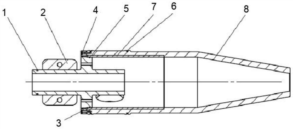
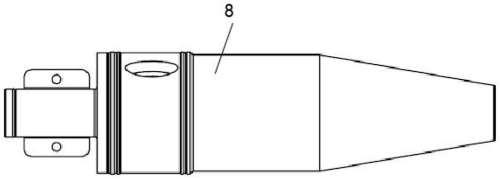
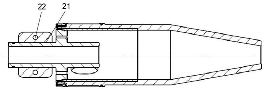
[0025] This embodiment provides a specific structure of an ultra-high pressure cyclone sand removal and separation device, such as Figure 1-3 As shown, an ultra-high pressure cyclone desanding separation device, including:

[0026] Mandrel 1, the outer surface of which is welded with baffle plate 2;

[0027] Conical barrel 8, which is fixedly fitted to one end of the mandrel 1, and the inner wall of the barrel 8 is inlaid with a bushing 7; and

[0028] The flow channel for sand removal is opened in the mandrel 1 , and the two ends of the flow channel are respectively set as a fluid inlet 3 and a fluid outlet 5 .

[0029] By adopting th...