Swirling flow producing apparatus, method of producing swirling flow, vapor phase generating apparatus, microbubble generating apparatus, fluid mixer and fluid injection nozzle

A technology for generating devices and fluids, which is applied in the direction of fluid mixers, mixers, injection devices, etc., can solve the problems of the outflow direction being limited to one direction, increase the amount of fluid processing, and low adaptability, and achieve the effect of improving processing efficiency

Inactive Publication Date: 2009-08-12
NAKATA COATING CO LTD
View PDF4 Cites 14 Cited by
  • Summary
  • Abstract
  • Description
  • Claims
  • Application Information

AI Technical Summary

Problems solved by technology

[0012] However, in any of the devices described in Patent Documents 1 to 4, there is a problem of low adaptability because no consideration is given to effectively generating swirl flow corresponding to each fluid when properties such as viscosity of the fluid are different.
[0013] In addition, in any of the devices described in these patent documents, the structure of the device is such that the introduced liquid can only flow out from one direction, so there is a process where the outflow direction is limited to one direction and the amount of fluid cannot be increased. quantity problem

Method used


Image

  • Swirling flow producing apparatus, method of producing swirling flow, vapor phase generating apparatus, microbubble generating apparatus, fluid mixer and fluid injection nozzle
  • Swirling flow producing apparatus, method of producing swirling flow, vapor phase generating apparatus, microbubble generating apparatus, fluid mixer and fluid injection nozzle
  • Swirling flow producing apparatus, method of producing swirling flow, vapor phase generating apparatus, microbubble generating apparatus, fluid mixer and fluid injection nozzle

Examples


no. 1 approach

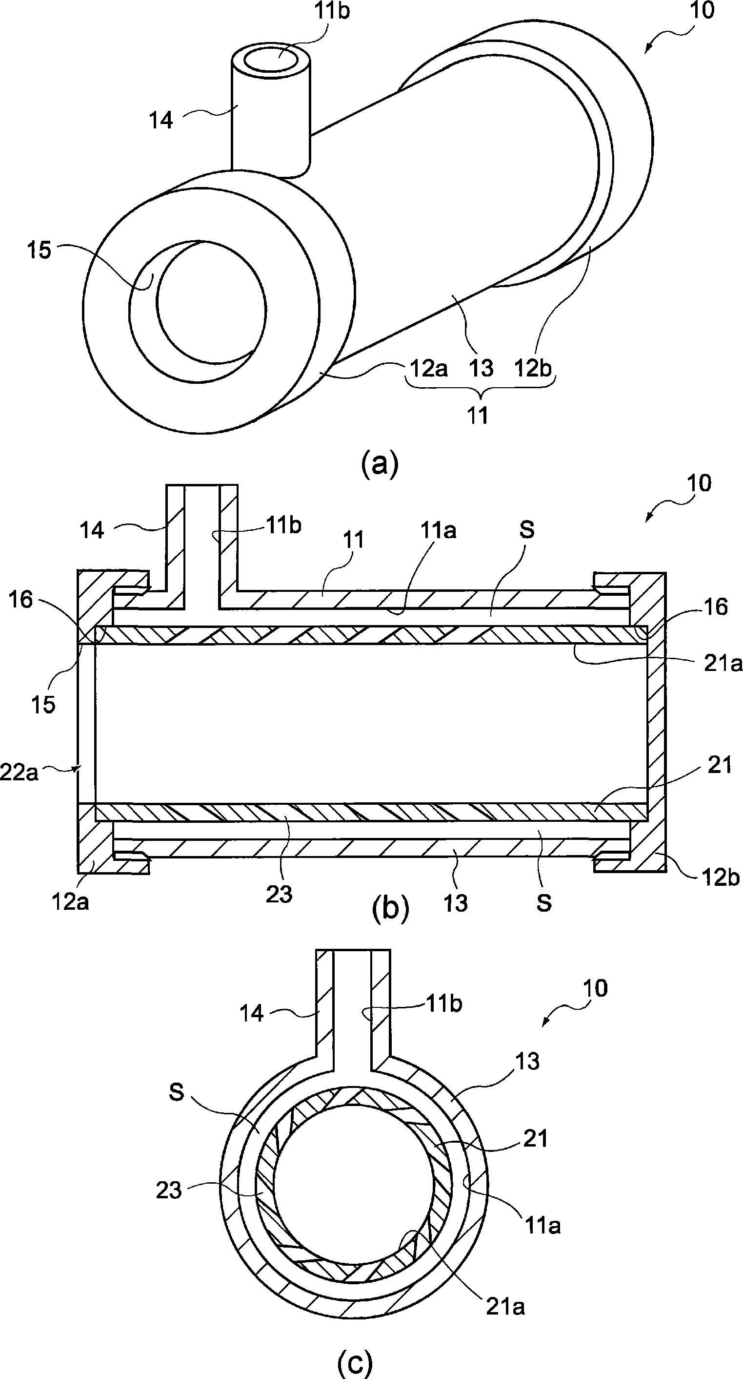
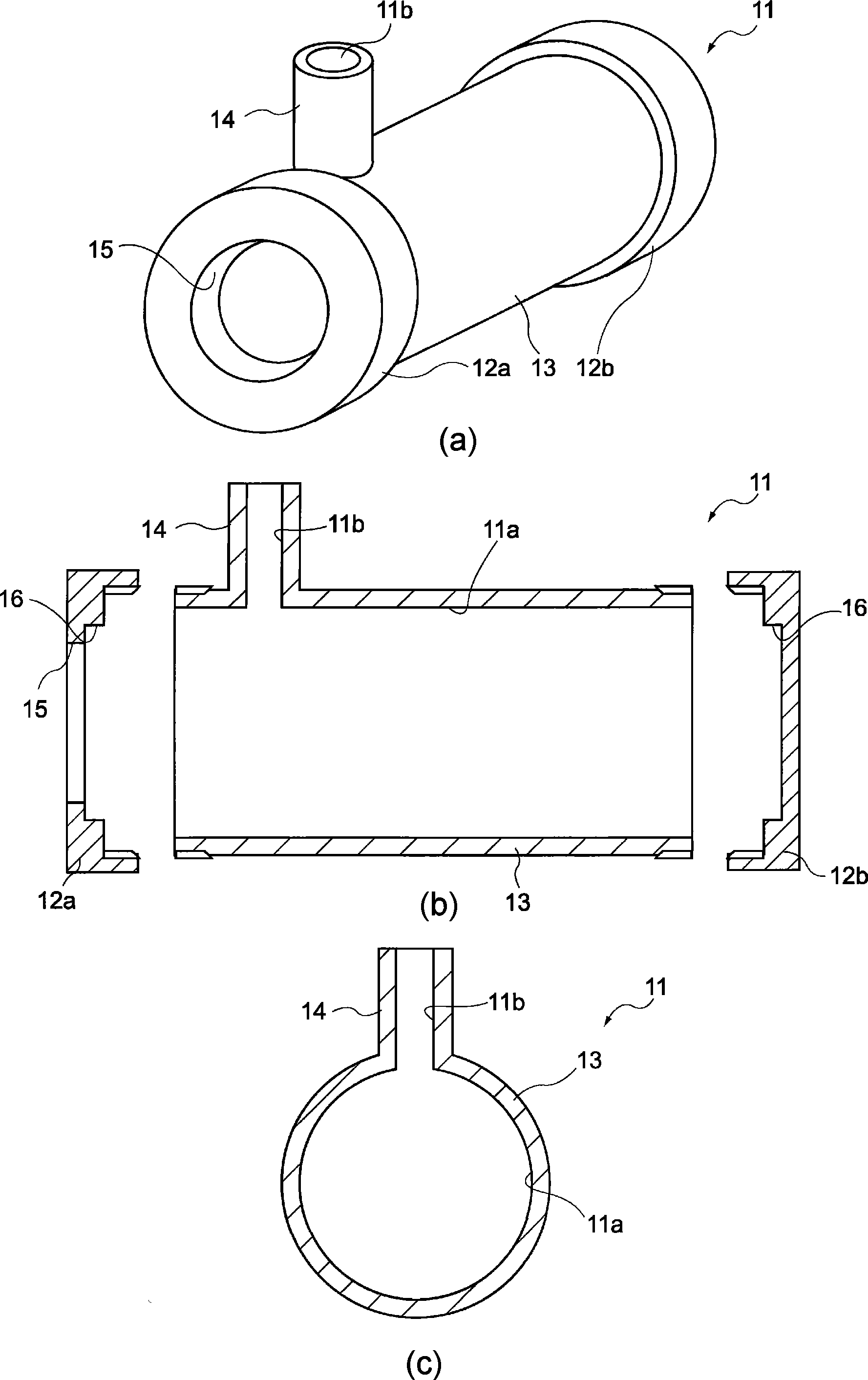
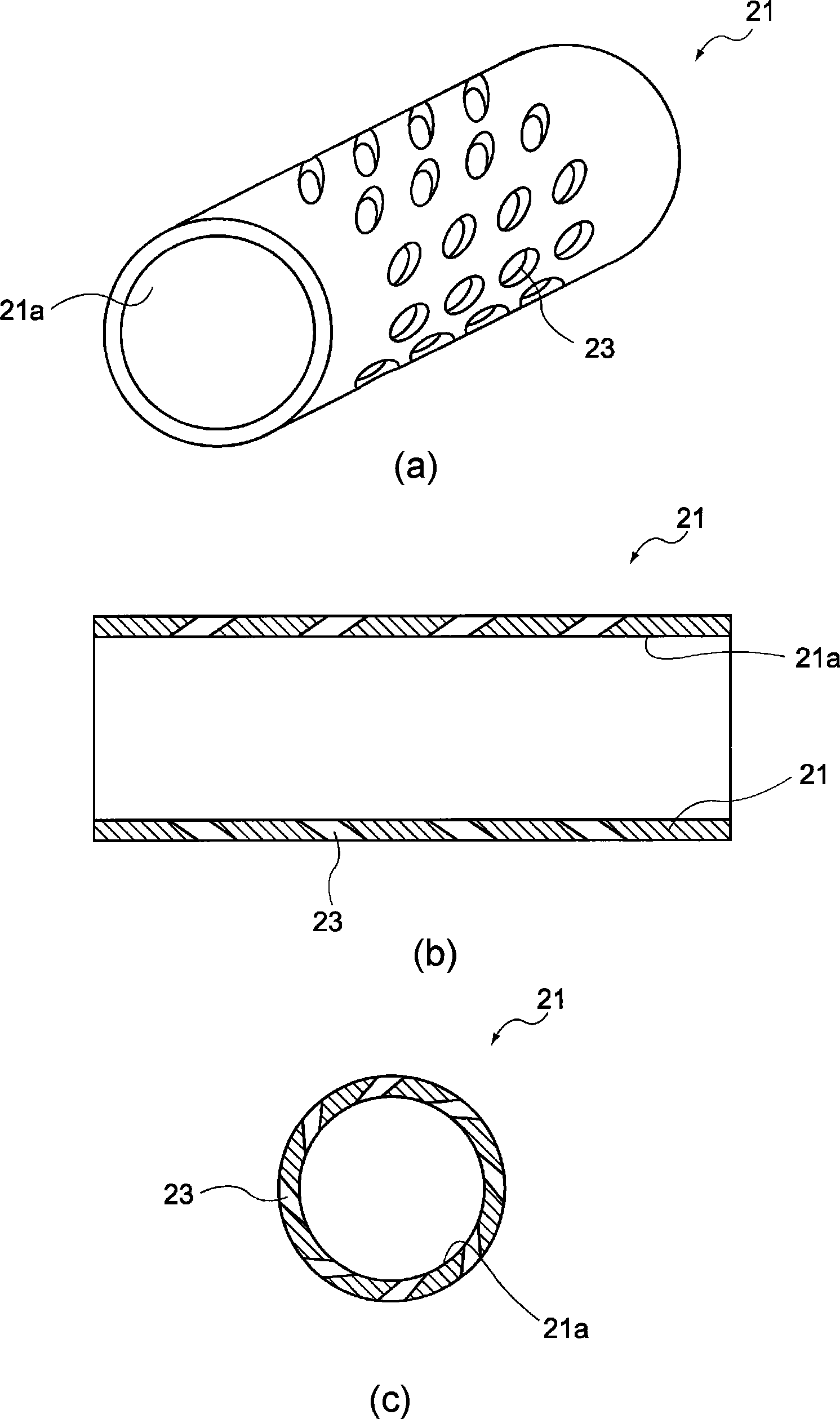
[0081] A first embodiment of the present invention is a swirl flow generation device and a swirl flow generation method using the swirl flow generation device, that is, the swirl flow generation device includes a housing and a cylindrical member, and the housing includes at least A cylindrical space part with one end open and a fluid introduction path open on the inner peripheral surface of the cylindrical space part, the cylindrical member is disposed in the cylindrical space part of the casing, and has at least a connection with the cylindrical space part. A cylindrical space portion opened at the end in the same direction as the opening direction and a hole portion opened on the peripheral wall of the cylindrical space portion, wherein the liquid fluid introduced from the fluid introduction path flows into the circle of the cylindrical member through the hole portion. In the space of the cylinder, swirling flow is generated, and it flows out from the casing and the cylindric...

no. 2 approach

[0144]A second embodiment of the present invention provides a gas phase generating device using the swirl flow generating device described in the first embodiment, and includes a housing and a cylindrical member. The housing includes at least one A cylindrical space part with an opening at the end of the cylindrical space part and a fluid introduction path opened at the inner peripheral surface of the cylindrical space part, the cylindrical member is arranged in the cylindrical space part of the casing, and has at least the opening of the cylindrical space part The cylindrical space portion opened at the end portion in the same direction and the hole portion opened on the peripheral wall of the cylindrical space portion allow the liquid fluid introduced from the fluid introduction path to flow into the cylindrical space of the cylindrical member through the hole portion. While generating a swirl in the inner part, let it flow out from the casing and the cylindrical member, ther...

no. 3 approach

[0149] A third embodiment of the present invention provides a micro-bubble generating device that uses the swirl flow generating device described in the first embodiment, and includes a housing and a cylindrical member. A cylindrical space part with at least one end opening and a fluid introduction path opened on the inner peripheral surface of the cylindrical space part, the cylindrical member is disposed in the cylindrical space part of the housing, and has at least one connection with the cylindrical space part. The cylindrical space portion opened at the end in the same direction as the opening direction of the cylindrical space portion and the hole portion opened on the peripheral wall of the cylindrical space portion, the liquid fluid introduced from the fluid introduction path flows into the cylinder of the cylindrical member through the hole portion. A swirl flow is generated in the cylindrical space, and while a gas phase is generated in the center of the swirl flow, t...


PUM


Abstract

There are provided a fluid injection nozzle, a fluid mixer, a microbubble generating apparatus, a vapor phase generating apparatus, a method of producing swirling flow, and a swirling flow producing apparatus that can be applied to any kind of fluid and can efficiently generate a swirling flow at high speed. The swirling flow producing apparatus includes a housing and a cylindrical member. The housing includes a cylindrical portion of which at least one end is opened, and a fluid introducing passage that is opened on an inner peripheral surface of the cylindrical portion. The cylindrical member is provided in the cylindrical portion of the housing. The cylindrical member includes a cylindrical portion of which at least one end in a direction corresponding to an opening direction of the cylindrical portion is opened, and holes formed in a peripheral wall of the cylindrical portion. A fluid introduced from the fluid introducing passage flows into the cylindrical portion of the cylindrical member through the holes so as to generate a swirling flow, and flows out from the housing and the cylindrical member.

Description

technical field [0001] The present invention relates to a swirl flow generation device, a swirl flow generation method, a gas phase generation device, a fine bubble generation device, a fluid mixing device, and a fluid injection nozzle. In particular, it relates to a swirl generator and method for efficiently generating a high-speed swirl, a gas phase generator, a microbubble generator, a fluid mixing device, and a fluid injection nozzle using the swirl generator. Background technique [0002] Conventionally, techniques for swirling liquids have been applied in various technical fields. [0003] For example, there is a separation device that can easily generate a stable swirl flow, reduce the pressure loss of the mixed fluid, improve the separation efficiency of the mixed fluid, and achieve compactness. More specifically, as Figure 23 As shown, there is disclosed a separating device that has a fluid passage 321 through which the mixed fluid F flows, and by rotating the mix...

Claims


Application Information

Patent Timeline
Patent Type & Authority Applications(China)
IPC IPC(8): B01F5/00B05B1/34
CPCB01F5/0475B01F2005/0636B01F2015/0221B01F2005/0637B01F5/0614B01F5/0256B01F5/0057B01F3/0446B01F2005/0621B01F2005/0632B01F2005/0017B01F23/232B01F2025/913B01F25/23B01F25/10B01F25/31425B01F25/3142B01F25/4317B01F25/4314B01F25/43195B01F25/431972B01F25/431971B01F35/715
Inventor 松野竹己中田章夫
Owner NAKATA COATING CO LTD
Why Eureka
Try Eureka