Toroidal ring ventilator

a ventilator and ring technology, applied in the field of medical devices for respiratory therapy and treatment, can solve the problems of insufficient regulation of inspired air/oxygen mixture, many potential complications of mechanical ventilation, blindness and other eye lesions, etc., and achieve the effect of reducing the negative intrapulmonary pressur

Inactive Publication Date: 2016-02-18
SIRIWARDENA MAPATUNAGE A +1
View PDF6 Cites 9 Cited by
  • Summary
  • Abstract
  • Description
  • Claims
  • Application Information

AI Technical Summary

Benefits of technology

[0017]An automatic flow sensor, which may be pre-set to detect flow pressure or carbon dioxide or oxygen levels in the FiO2 mix being delivered to the patient, is preferably positioned further along the flow path, or the like. The automatic flow sensor is in communication with a vortex generator control (which may be a programmable logic controller or the like), which drives a vortex generator trigger circuit to operate the vortex ring generator. Further, the inspiratory effort of the patient also triggers the automatic flow sensor, which, in turn, generates a triggering signal for the actuation of the vortex ring generator (through the vortex generator control and the vortex generator trigger circuit). The inspiratory effort of the patient allows propulsion of mini ring vortices into the intrapulmonary space during the inspiratory phase, thereby augmenting the negative intrapulmonary pressure generated by the patient's effort.

Problems solved by technology

The drawbacks of all of the above ventilators are: the use of positive pressures, which may lead to barotrauma to the lung tissue which leads to chronic lung disease (CLD); and inadequate regulation of inspired air / oxygen mixture (FiO2).
Low FiO2 may cause hypoxemia, and high FiO2 may cause direct oxygen toxicity to the lungs and remote toxicity to the eyes of the premature infants, which leads to Retinopathy of Prematurely (ROP), which may cause blindness and other eye lesions.
Further, although often a lifesaving technique, mechanical ventilation carries many potential complications including pneumothorax, airway injury, alveolar damage, and ventilator-associated pneumonia, among others.
Further, conventional mechanical ventilators, as described above, are typically bulky, often consisting of various pieces of equipment which take up an entire room's worth of space.
Such a system is not easily transportable, particularly in emergency situations.

Method used


Image

  • Toroidal ring ventilator
  • Toroidal ring ventilator
  • Toroidal ring ventilator

Examples


Embodiment Construction

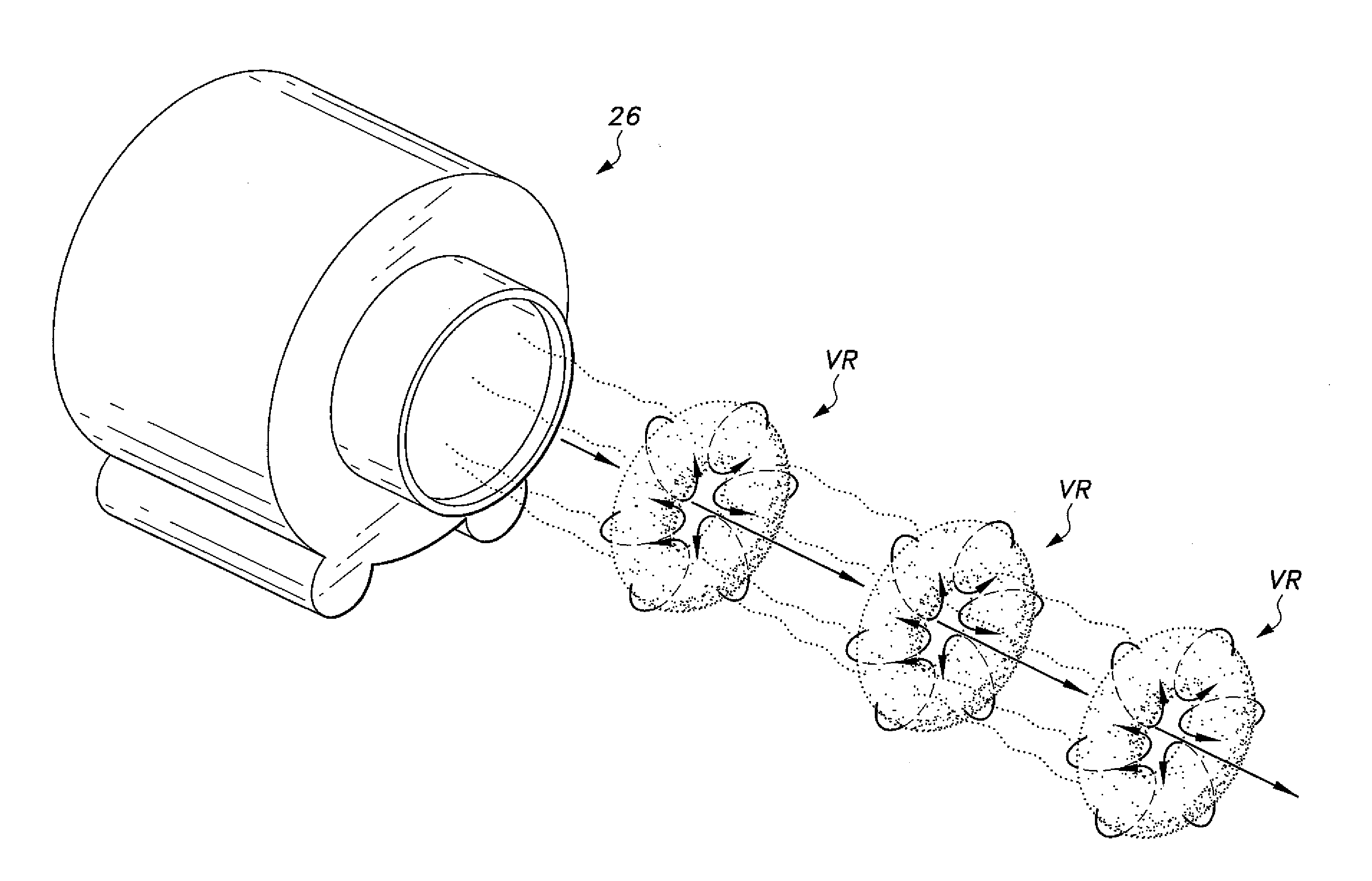
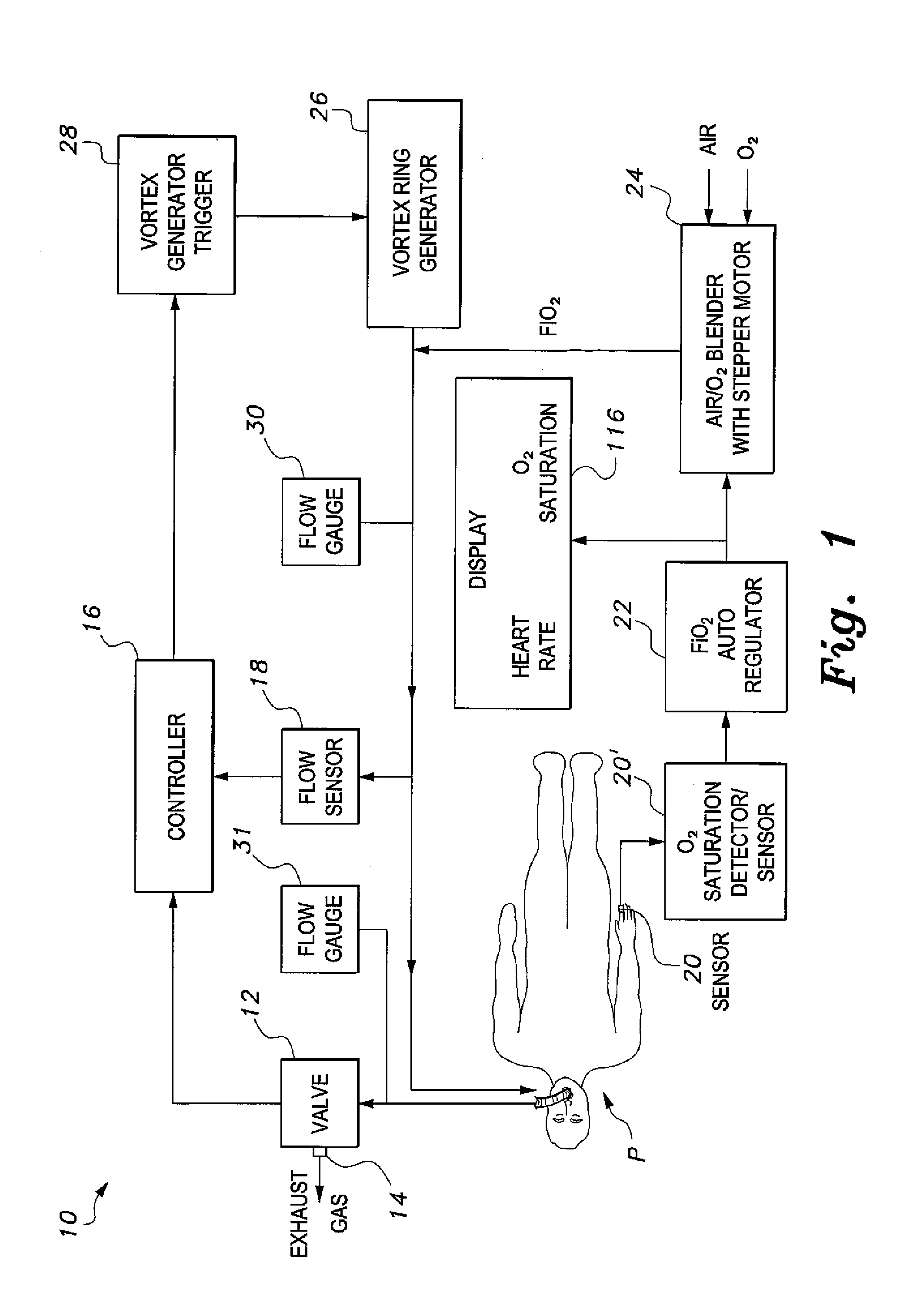
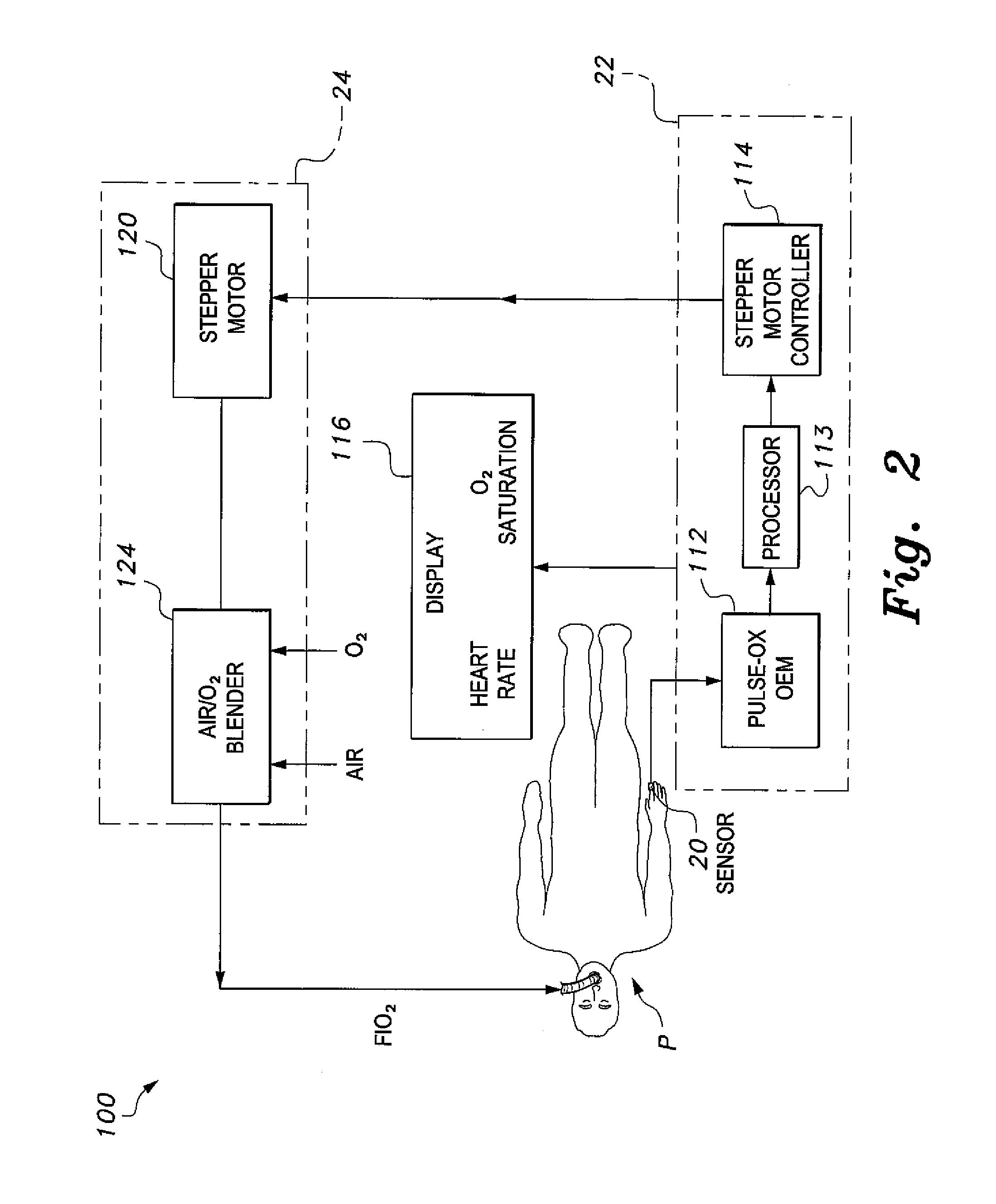
[0029]The present invention is directed towards a mechanical ventilator system 10. As best shown in FIGS. 1 and 2, the mechanical ventilator system 10 includes a vortex generator 26 in fluid communication with an air oxygen blender 24 for delivering oxygen to a patient. The system is preferably portable and provides a controllable oxygen flow to a patient, ranging from neonatal patients to adults. The system is actuated by the inspiratory effort of an intubated patient. The inspiratory effort of the patient generates a negative air pressure in the range of approximately −4 mm to −6 mm Hg or greater. During the expiratory phase, the mechanical ventilator 10 remains idle, allowing the patient to exhale exhalation gases via an exhalation valve 14 (as will be described in greater detail below) with minimal resistance. Preferably, vortex ring generator 26, auto-regulated air / oxygen blender 24, the timing control mechanism (controller) 16, and the digital display 116 are all encased withi...


PUM


Abstract

The mechanical ventilator system is a compact and portable artificial respiration system. A vortex ring generator delivers a FiO2 mix from an air-oxygen blender to a patient's alveoli via an endotracheal tube during the s patient's inhalations, but remains idle during the patient's exhalations. Exhaust gases generated by the patient are released through an exhaust gas valve. During operation, the patient's oxygen saturation level is measured and kept in communication to receive oxygen saturation level signals and to control the oxygen proportion of the FiO2 mix. A pressure flow sensor is fluidly coupled with the patient's airway to control actuation of the vortex generator. The flow sensor is coupled with a controller, which actuates a vortex generator trigger circuit in communication with the vortex ring generator.

Description

CROSS-REFERENCE TO RELATED APPLICATION[0001]This application is a continuation-in-part of application Ser. No. 14 / 055,705, filed Oct. 16, 2013, now pending, which is a continuation-in-part of application Ser. No. 12 / 076, 751, filed Mar. 21, 2008, now abandoned, which claims the benefit of U.S. Provisional Patent Application Ser. No. 60 / 996,615, filed Nov. 27, 2007.BACKGROUND OF THE INVENTION[0002]1. Field of the Invention[0003]The present invention relates to medical devices for respiratory therapy and treatment, and particularly to a mechanical ventilator system that propels mini ring or toroidal vortices into the intrapulmonary space during the inspiratory phase of breathing, while maintaining the intrapulmonary pressure below the atmospheric pressure. These devices are intended to ease the respiratory effort of the patient by augmenting the negative intrapulmonary pressure generated by the patient during the inspiratory phase of breathing.[0004]2. Description of the Related Art[0...

Claims


Application Information

Patent Timeline
Patent Type & Authority Applications(United States)
IPC IPC(8): A61M16/00A61M16/04A61M16/10
CPCA61M16/0069A61M16/0003A61M16/04A61M2230/205A61M2016/0027A61M2016/003A61M2205/3331A61M16/1005A61B5/02416A61B5/0836A61B5/087A61B5/1455A61B5/14552A61B5/4836A61M16/12A61M2016/0024A61M2016/0039A61M2016/103A61M2202/0208A61M2205/502A61M2206/16A61M2230/06A61B5/0205A61B5/6801A61B5/742A61M16/125A61M16/024A61M2230/005A61M2202/0007
Inventor SIRIWARDENA, MAPATUNAGE A.RAO, CHAMKURKISHTIAH P.
Owner SIRIWARDENA MAPATUNAGE A
Why Eureka
Try Eureka