Repositioning and fixation system for bone fragments

a fixation system and bone fragment technology, applied in the field of repositioning and fixation system, can solve the problems of difficult to fix the bone fragments in the final position and inability to move the bone plates relative to each other, and achieve the effect of widening the distance and widening the width

Active Publication Date: 2010-07-15
WOLTER DIETMAR
View PDF12 Cites 37 Cited by
  • Summary
  • Abstract
  • Description
  • Claims
  • Application Information

AI Technical Summary

Benefits of technology

[0021]In another embodiment, the repositioning and fixation system again comprises four bone plates, but these each have a connector element arranged at the center and a connector element arranged at the periphery of the bone plate. Two bone plates are in each case interconnected at the center to form a scissors-type structure. The two scissor structures are interconnected via the peripheral connector elements to form a slidable lattice structure. If necessary, a plurality of scissors-type structures can be joined up to form a longer slidable lattice. With a repositioning and fixation system in the form of a slidable lattice, it is possible to bridge a greater distance between the fracture site and the point where the forceps are engaged. It is also possible for slidable lattices to be extended in width by attachment of further bone lattices, resulting in a slidable lattice of

Problems solved by technology

A disadvantage of the known repositioning and fixation system is that in many cases, when the bone fragments have been repositioned by pivoting of the bone plates,

Method used


Image

  • Repositioning and fixation system for bone fragments
  • Repositioning and fixation system for bone fragments
  • Repositioning and fixation system for bone fragments

Examples


Embodiment Construction

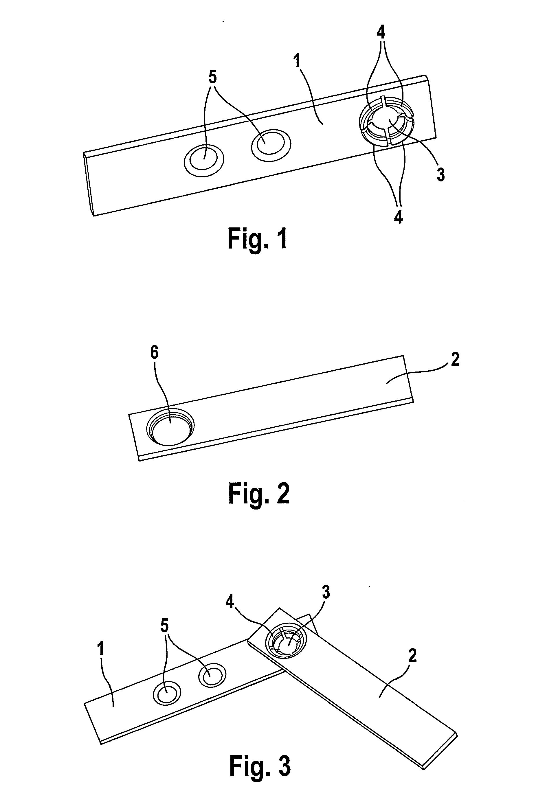
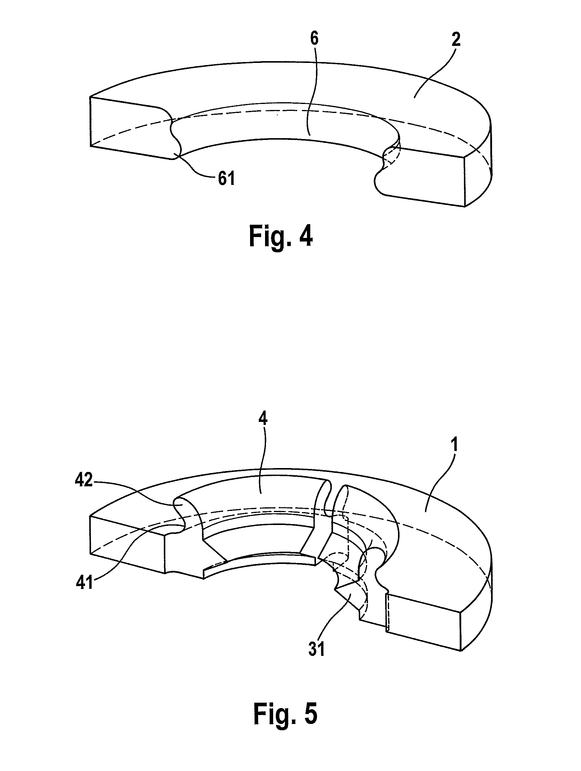
[0038]The repositioning and fixation system comprises a first bone plate 1 (FIG. 1) and a second bone plate 2 (FIG. 2). The first bone plate 1 has a bore 3, and four projections 4 arranged at the circumference of the bore 3. The projections 4 form a connector element for connection to another bone plate. The bone plate 1 has further bores 5. The second bone plate 2 is provided with an opening 6. The opening 6 forms a connector element for the connection to another bone plate.

[0039]The projections 4 comprise a segment 41 close to the bone plate and a segment 42 remote from the bone plate. The segments 42 of the projections 4 remote from the bone plate can be enclosed by an imaginary circle whose diameter is greater than the smallest diameter of the opening 6. The smallest diameter of the opening 6 is formed by a bead 61 in the wall of the opening. The segments 41 of the projections 4 close to the bone plate can be enclosed by an imaginary circle whose diameter corresponds to the smal...


PUM


Abstract

The repositioning and fixation system according to the invention comprises at least two bone plates that are designed to be interconnected. Each bone plate is provided with a connector element for connection to another bone plate. The connector element of a first bone plate comprises a plurality of projections. The connector element of a second bone plate comprises an opening. In a first connection state, the projections engage in the opening and produce a hinge-type connection between the first bone plate and the second bone plate. In a second connection state, the projections are tensioned and produce a rigid connection between the first bone plate and the second bone plate. With the repositioning and fixation system according to the invention, bone fragments secured to the bone plates can be repositioned by pivoting of the bone plates. Once the bone fragments have been brought to their final position, the projections can be tensioned in such a way that the bone plates are rigidly interconnected.

Description

REFERENCE TO RELATED APPLICATIONS[0001]This application is a national stage application under 35 USC 371 of International Application No. PCT / EP2007 / 010898, filed Dec. 12, 2007, which claims the priority of German Patent Application No. 10 2006 062 164.6, filed Dec. 22, 2006, the contents of which prior applications are incorporated herein by reference.FIELD OF THE INVENTION[0002]The invention relates to a repositioning and fixation system with which bone fragments can be repositioned and then fixed.BACKGROUND OF THE INVENTION[0003]For over a century, bone fragments have been fixed relative to each other with the aid of bone plates, screws and nails. The fixation of bone fragments by means of traditional bone plates requires that the bone fragments are already repositioned, that is to say are in the correct position relative to each other. The traditional bone plate is placed onto the repositioned bone fragments and is secured to the bone fragments by screws or nails.[0004]A reposit...

Claims


Application Information

Patent Timeline
IPC IPC(8): A61B17/80
CPCA61B17/80A61B17/8057A61B2017/00477A61B17/8066A61B17/8085A61B17/8061
Inventor WOLTER, DIETMAR
Owner WOLTER DIETMAR
Why Eureka
Try Eureka