PV Wind Performance Enhancing Methods

a technology of enhancing methods and wind power, which is applied in the safety of solar heat collectors, lighting and heating equipment, instruments, etc., can solve the problems of easy installation of light-weight pv assemblies, achieve enhanced pressure equalization between upper and lower surfaces of pv modules of the array of pv modules, and reduce uplift forces

Inactive Publication Date: 2010-07-15
SUNPOWER CORPORATION
View PDF53 Cites 36 Cited by
  • Summary
  • Abstract
  • Description
  • Claims
  • Application Information

AI Technical Summary

Benefits of technology

[0010]A seventh aspect of the invention is directed to a PV installation comprising a support surface, an array of PV modules, comprising PV modules having upper and lower surfaces, and PV module supports supporting the PV modules on and generally parallel to the support surface. The array of PV modules defines a circumferentially closed perimeter. A perimeter air deflector is positioned outwardly of the perimeter. An array air volume is V defined between the array of PV modules and the support surface. A module gap area MGA is defined between the PV modules. A perimeter gap area PGA is defined along the perimeter between the PV modules and the support surface. The PV installation defines a ratio R, R=V divided by (MGA+PGA), R being less than a chosen ratio, the chosen ratio being no more than 20, whereby pressure equalization between upper and lower surfaces of PV modules of the array of PV modules is enhanced.
[0011]An eighth aspect of the invention is directed to a PV installation comprising a support surface, an array of PV modules, comprising PV modules having upper and lower surfaces, and PV module supports supporting the PV modules on and generally parallel to the support surface. The array of PV modules defines a circumferentially closed perimeter. A perimeter air deflector is positioned outwardly of the perimeter. An array air volume is V defined between the array of PV modules and the support surface. An interior array gap area IGAP is defined as the sum of all gap areas between solid surfaces located within the array when viewed from vertically above the array. A perimeter gap area PGAP is defined as the lesser of 1) the area between the top edges of the PV modules and deflectors and the roof surface or 2) the area between the top edges of the PV modules and any perimeter deflector device. The PV installation defines a ratio R, R=V divided by (IGAP+PGAP), R being less than a chosen ratio, the chosen ratio being no more than 20, whereby pressure equalization between upper and lower surfaces of PV modules of the array of PV modules is enhanced.
[0012]A ninth aspect of the invention is directed to a PV installation comprising a support surface, an array of PV assemblies and PV assembly supports supporting the PV assemblies on the support surface. The array of PV assemblies comprises PV modules having upper and lower surfaces, at least some of said PV assemblies comprising (1) an inclined PV module having a lower edge, an upper edge and inclined side edges joining the lower and upper edges, and (2) an air deflector having deflector side edges and an upper deflector edge opposite the upper edge of the inclined PV module and defining a gap therebetween. The array of PV assemblies defines a circumferentially closed perimeter. An array air volume V is defined between the array of PV assemblies and the support surface. A module gap area MGA is defined between the PV modules. A perimeter gap area PGA is defined along the perimeter between the PV assemblies and the support surface. A deflector / deflector gap area D / DGA is defined between opposed ones of the inclined deflector side edges. An air deflector gap area ADGA is defined between the upper edges of the air deflectors and the upper edges of the PV modules. The PV installation defines a ratio R, R=V divided by (MGA+ADGA+PGA+D / DGA), R being less than a chosen ratio, the chosen ratio being no more than 20, whereby pressure equalization between upper and lower surfaces of PV modules of the array of PV modules is enhanced.
[0013]A tenth aspect of the invention is directed to a PV installation comprising a support surface, an array of PV assemblies and PV assembly supports supporting the PV assemblies on the support surface. The array of PV assemblies comprises PV modules having upper and lower surfaces, at least some of said PV assemblies comprising (1) an inclined PV module having a lower edge, an upper edge and inclined side edges joining the lower and upper edges, and (2) an air deflector having deflector side edges and an upper deflector edge opposite the upper edge of the inclined PV module and defining a gap therebetween. The array of PV assemblies defines a circumferentially closed perimeter. An array air volume V is defined between the array of PV assemblies and the support surface. An interior array gap area IGAP is defined as the sum of all gap areas between solid surfaces located within the array when viewed from vertically above the array. A perimeter gap area PGAP is defined as the lesser of 1) the area between the top edges of the PV modules and deflectors and the roof surface or 2) the area between the top edges of the PV modules and any perimeter deflector device. The PV installation defines a ratio R, R=V divided by (IGAP+PGAP), R being less than a chosen ratio, the chosen ratio being no more than 20. Whereby pressure equalization between upper and lower surfaces of PV modules of the array of PV modules is enhanced. The PV installation may also include side air deflectors along a portion of the perimeter opposite the inclined side edges of a plurality of said inclined PV modules and a deflector / module gap area D / MGA between the side air deflectors and the perimeter; whereby when D / MGA is less than PGA, then a ratio RX, RX=V divided by (MGA+D / MGA), is less than the chosen ratio.
[0014]An eleventh aspect of the invention is directed to a PV installation comprising a support surface, a PV assembly and a PV assembly support supporting the PV assembly on and directly opposite the support surface. The PV assembly comprises a front edge, a back edge, and first and second side edges joining the front and back edges, the edges defining a PV assembly periphery. The PV assembly periphery and the support surface define a preliminary gap area therebetween. At least a first portion of the PV assembly periphery is spaced apart from the support surface by at least a first distance. An air volume V is defined between the PV assembly and the support surface. The PV assembly comprises an air deflector located along at least substantially the entire first portion of the periphery and blocking a portion of the preliminary gap area so to define an effective gap area (EGA) opening into the air volume. Whereby pressure equalization between upper and lower surfaces of PV modules of the array of PV modules is enhanced while reducing uplift forces created by wind flow over the PV modules.

Problems solved by technology

Fourth, lightweight PV assemblies are easier to install than assemblies that rely on ballast weight to counteract wind uplift forces.

Method used


Image

  • PV Wind Performance Enhancing Methods
  • PV Wind Performance Enhancing Methods
  • PV Wind Performance Enhancing Methods

Examples


Embodiment Construction

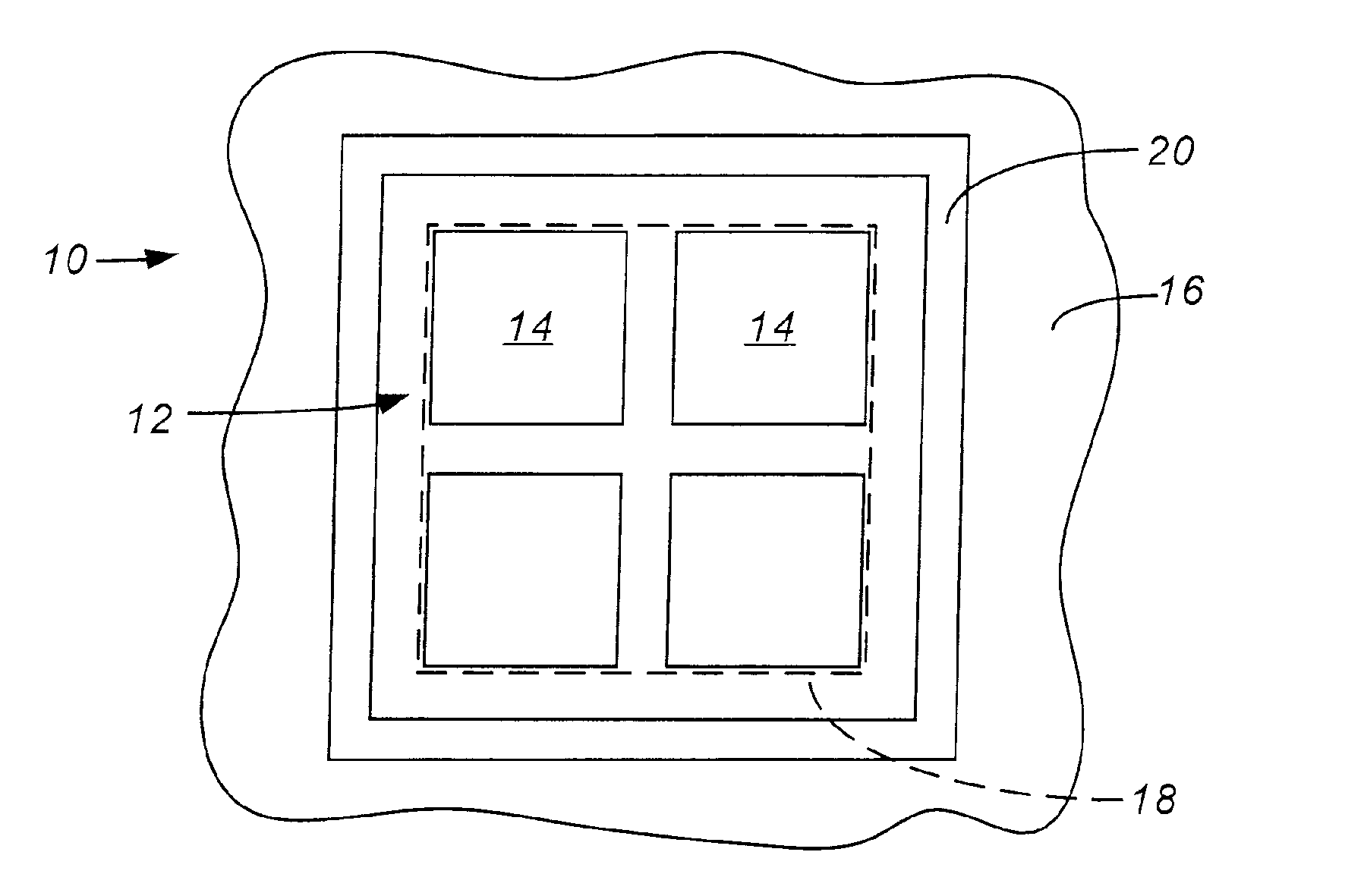
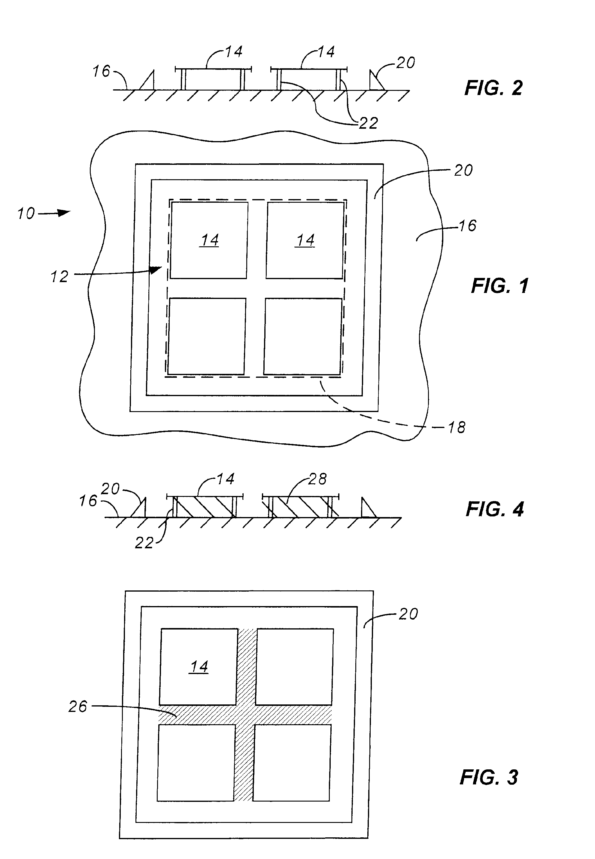
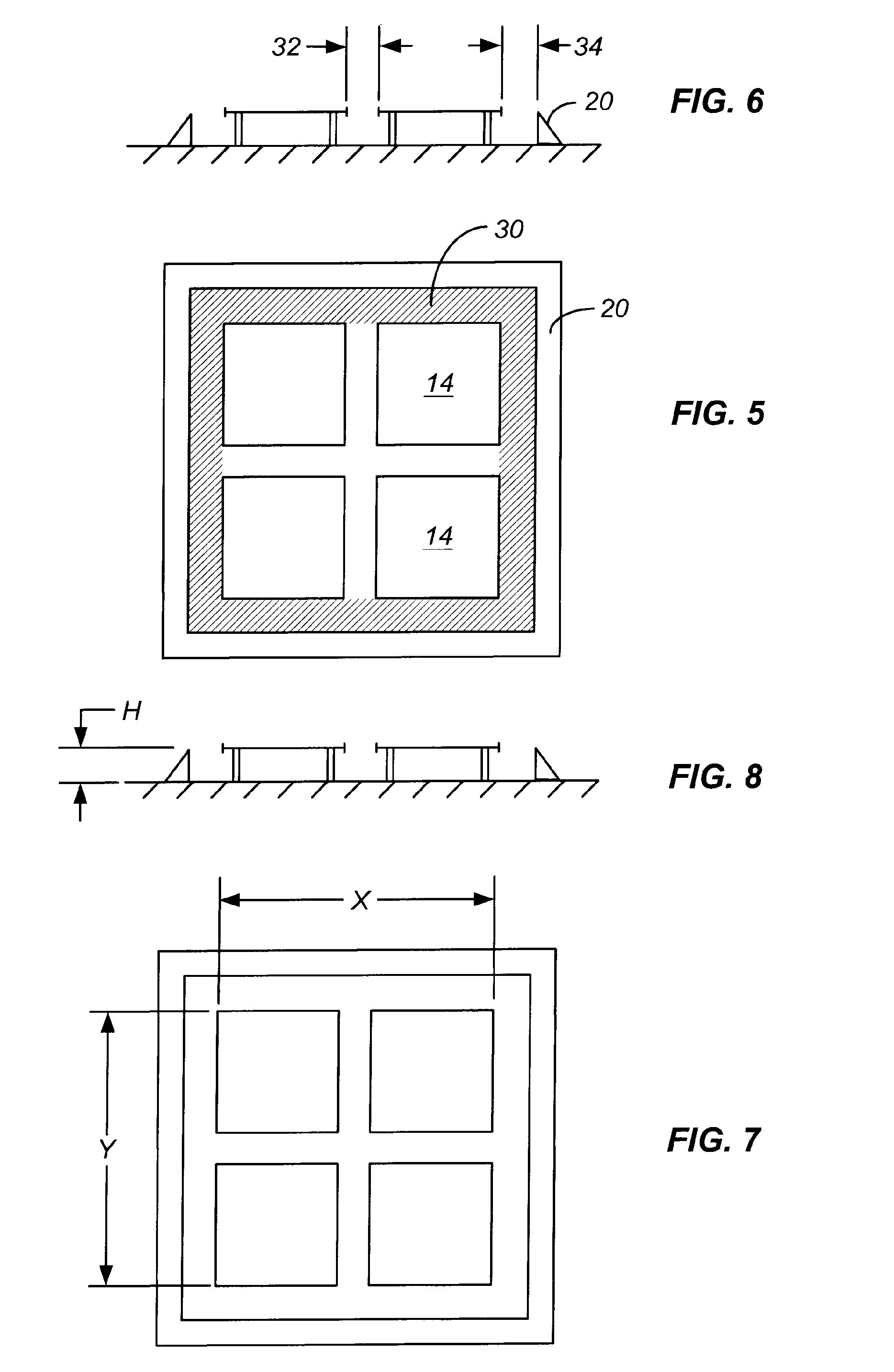
[0053]FIGS. 1 and 2 are top plan and side elevational views of a PV installation 10, installation 10 including an array 12 of PV modules 14 supported by a support surface 16, typically the roof of a building. Array 12 of PV modules 14 define a circumferentially closed perimeter 18. Installation 10 also includes a perimeter air deflector 20 surrounding and spaced apart from perimeter 18 and PV modules supports 22 supporting PV modules 14 above a support surface 16. The general construction of PV installation 10 may be conventional, such as disclosed in one or more of the above-referenced patents with exemplary possible modifications discussed below. For example, PV modules 14 are preferably interconnected to one another to enhance resistance to wind uplift forces. The number, shape, orientation and arrangement of PV modules 14, as well as perimeter air deflector 20 and supports 22, may be changed from that illustrated, PV installation 10 being a simplified exemplary installation used...


PUM


Abstract

Pressure equalization between upper and lower surfaces of PV modules of an array of PV modules can be enhanced in several ways. Air gaps opening into the air volume, defined between the PV modules and the support surface, should be provided between adjacent PV modules and along the periphery of the array. The ratio of this air volume to the total area of the air gaps should be minimized. Peripheral wind deflectors should be used to minimize aerodynamic drag forces on the PV modules. The time to equalize pressure between the upper and lower surfaces of the PV modules should be maintained below, for example, 10-20 milliseconds. The displacement created by wind gusts should be limited to, for example, 2-5 millimeters or less. For inclined PV modules, rear air deflectors are advised for each PV module and side air deflectors are advised for the periphery of the array.

Description

CROSS-REFERENCE TO OTHER APPLICATIONS[0001]This application is a divisional of copending U.S. patent application Ser. No. 10 / 922,117, filed 19 Aug. 2004, which application claims the benefit of U.S. Provisional Application No. 60 / 496,476, filed 20 Aug. 2003, and U.S. Provisional Application No. 60 / 517,438, filed 5 Nov. 2003, which are incorporated by reference herein.FEDERALLY SPONSORED RESEARCH OR DEVELOPMENT[0002]None.BACKGROUND OF THE INVENTION[0003]Air moving across an array of photovoltaic (PV) assemblies mounted to the roof of a building, or other support surface, creates wind uplift forces on the PV assemblies. Much work has been done in the design and evaluation of arrays of PV assemblies to minimize wind uplift forces. See U.S. Pat. Nos. 5,316,592; 5,505,788; 5,746,839; 6,061,978; 6,148,570; 6,495,750; 6,534,703; 6,501,013 and 6,570,084. Reducing wind uplift forces provides several advantages. First, it reduces the necessary weight per unit area of the array. This reduces o...

Claims


Application Information

Patent Timeline
Patent Type & Authority Applications(United States)
IPC IPC(8): G06F19/00F24J2/46F24J2/52H01LH01L25/00
CPCF24J2/461F24J2/4638F24J2/5235F24J2/5237F24J2/5239H02S20/24Y02B10/12Y02B10/20Y02E10/47H02S40/00F24J2/5266F24S30/20F24S25/15F24S25/16F24S25/11F24S40/20F24S40/85F24S2025/01Y02E10/50Y02B10/10H02S99/00H02S20/00H02S20/23H02S30/10
Inventor DINWOODIE, THOMAS L.O'BRIEN, COLLEEN A.NEFF, DAVID E.
Owner SUNPOWER CORPORATION
Why Eureka
Try Eureka