
Test pattern compression

a test pattern and compression technology, applied in the direction of resistance/reactance/impedence, testing circuit, instruments, etc., can solve the problems of large test set size and relatively long test time, large test set size and excessive storage requirements, etc., to facilitate understanding

Inactive Publication Date: 2010-07-15
IBM CORP
View PDF2 Cites 14 Cited by
  • Summary
  • Abstract
  • Description
  • Claims
  • Application Information

AI Technical Summary

Benefits of technology

This patent describes a way to compress testing patterns used in computer hardware design. By replacing certain parts of the original pattern with randomly chosen ones, the method improves the effectiveness of testing while maintaining high levels of fault coverage. If there are any errors detected during this process, the method also allows for easy replacement of the affected part of the pattern. Overall, this technique helps improve the accuracy and efficiency of software development.

Problems solved by technology

The technical problem addressed in this patent text relates to improving test pattern compression for efficient and accurate defect testing of complex integrated circuits. Current compression techniques such as pattern-merging have limitations when dealing with larger circuit densities and may lead to significantly longer testing times due to the requirement of a large set of test patterns. There is thus a need for better test pattern compression methods that address these issues.

Method used


Image

  • Test pattern compression
  • Test pattern compression
  • Test pattern compression

Examples


Embodiment Construction

[0022]The particular values and configurations discussed in these non-limiting examples can be varied and are cited merely to illustrate at least one embodiment and are not intended to limit the scope of the invention.

[0023]In the following discussion, numerous specific details are set forth to provide a thorough understanding of the present invention. Those skilled in the art will appreciate that the present invention may be practiced without such specific details. In other instances, well-known elements have been illustrated in schematic or block diagram form in order not to obscure the present invention in unnecessary detail. Additionally, for the most part, details concerning network communications, electro-magnetic signaling techniques, user interface or input / output techniques, and the like, have been omitted inasmuch as such details are not considered necessary to obtain a complete understanding of the present invention, and are considered to be within the understanding of pe...


PUM


Abstract

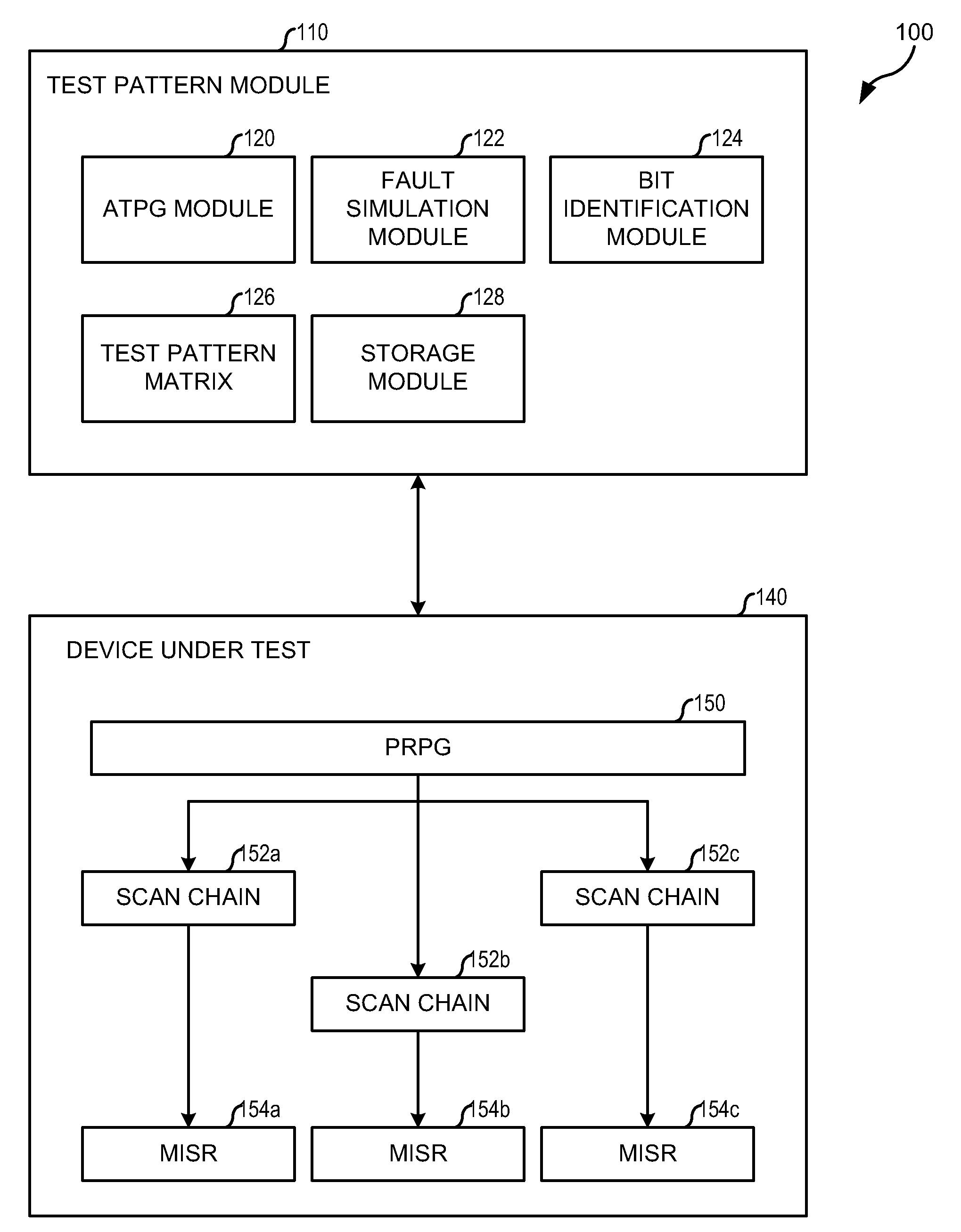
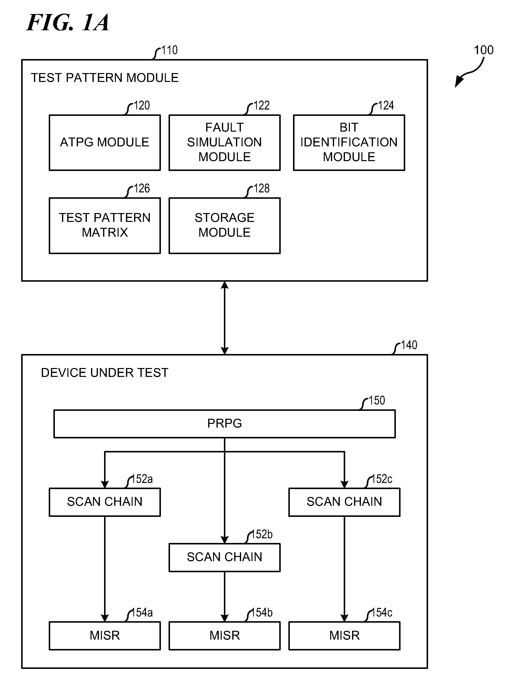
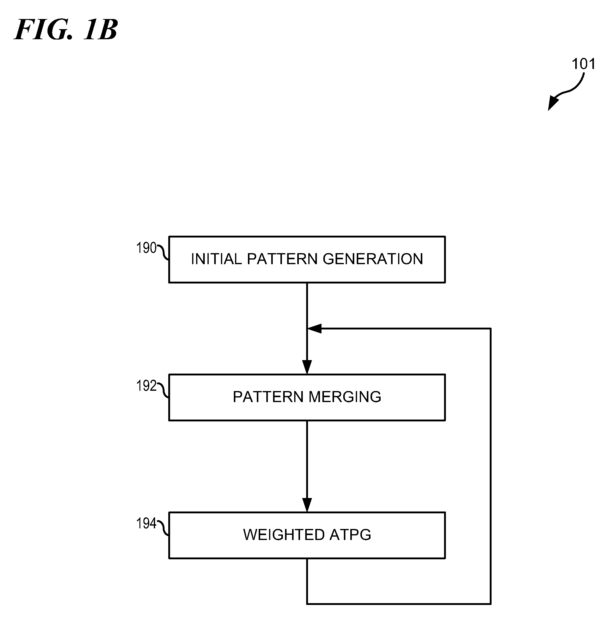
A method for test pattern compression generates a first test pattern comprising a plurality of bits. The method identifies bits comprising a don't-care bit value in the first test pattern and replaces the identified bit values with random bit values, to generate a second test pattern. The method determines a fault coverage level of the second test pattern. In the event the determined fault coverage level of the second test pattern exceeds a predetermined individual test pattern fault coverage level, for at least one bit position in the second test pattern corresponding to a replaced identified bit value and detecting at least one fault, the method exchanges the don't care value in the bit position in the first test pattern with the bit value in the corresponding bit position in the second test pattern. The method merges subsequent test patterns that increase fault coverage with the second test pattern.

Description


Claims


Application Information

Patent Timeline
Owner IBM CORP
Learn More