
Lifting-cover type frying-roasting device

a lifting cover and electric heating technology, which is applied in the direction of roasters/grills, frying pans, kitchen equipment, etc., can solve the problems of difficult cleaning of the wall behind the electrical heating device, and achieve the effect of convenient accommodation, use, and convenient assembly and transportation

Active Publication Date: 2010-07-22
TSANN KUEN CHINA ENTERPRISE
View PDF29 Cites 6 Cited by
  • Summary
  • Abstract
  • Description
  • Claims
  • Application Information

AI Technical Summary

Benefits of technology

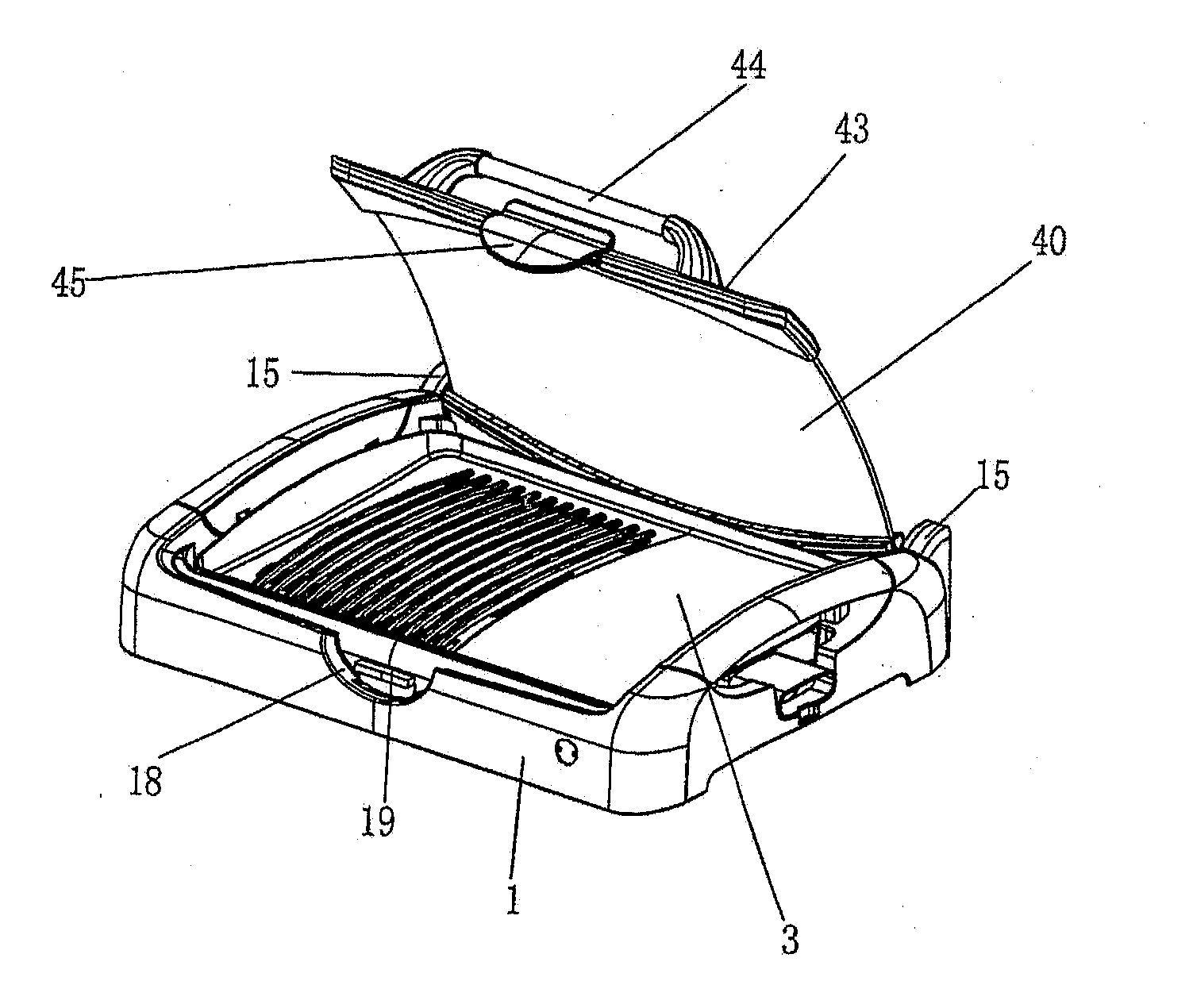
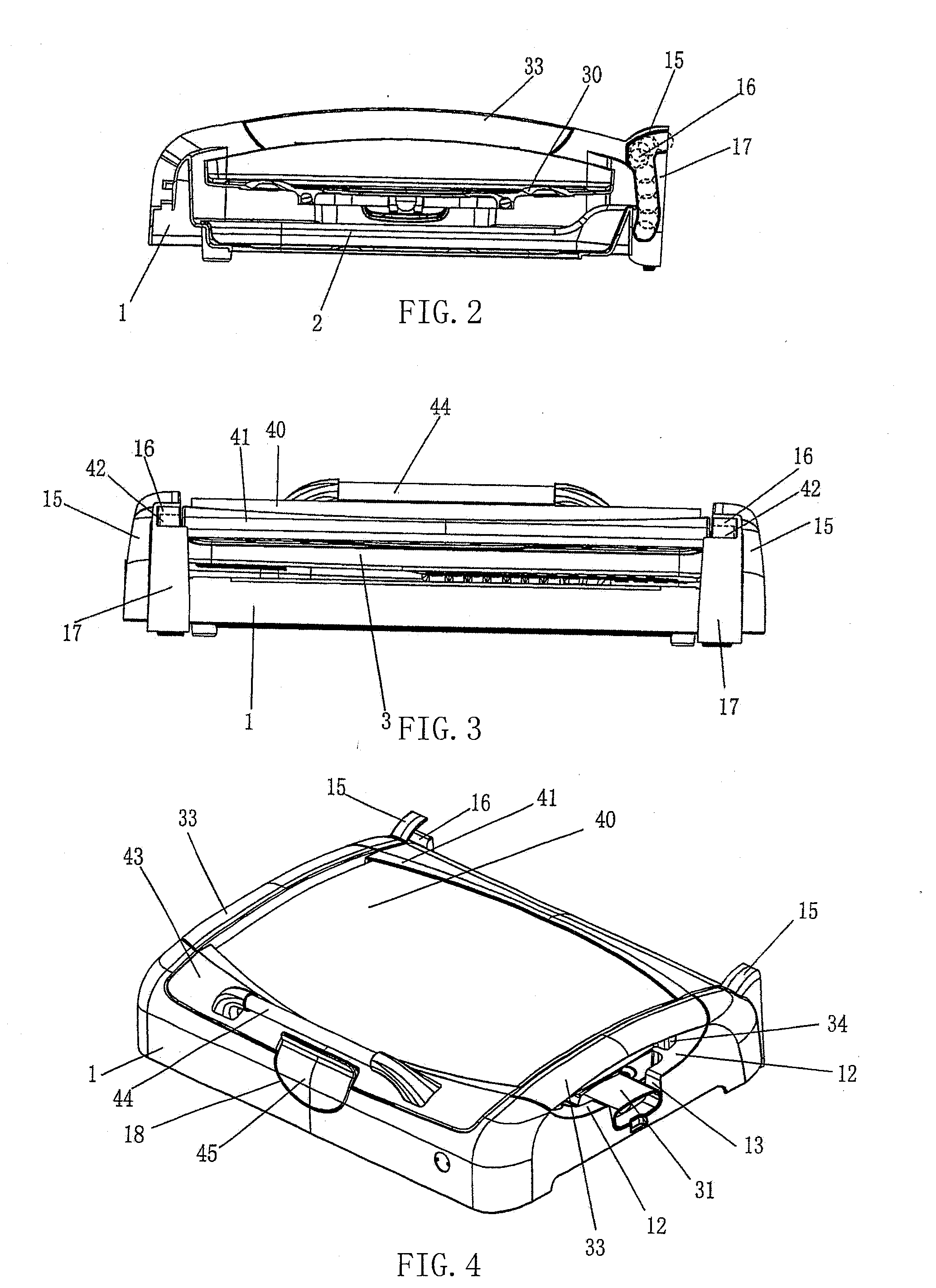
[0010]The lifting-cover type frying-roasting device of the present invention, wherein there is respectively a short jointed shaft extending outward at the back end of two sides of the upper cover; and there is respectively a opening orbit disposed on the two sides of the back end of the bottom base; the two jointed shafts are inserted in the orbit corresponding to the back of the bottom base to form hinging connection, the open of said upper cover can prevent the hot oil spattering to the wall behind; the two jointed shafts can be withdrawn from the orbit corresponding to the back end of the bottom base, then remove said upper cover. So the upper cover can be hinged joint with the bottom base and separated from the bottom base for cleaning. There is respectively a boss extending backwards at two sides of the back end of the bottom base, a r-shaped orbit whose opening is from its back end and extends toward its front lower part is respectively set in the inside of each boss; and there is a blocking wall that extends from the back end to the inside of each boss, the height of two blocking walls is lower than the opening of the r-shaped orbit; when the upper cover is opened, the two jointed shafts fall to the bottom end of the corresponding orbit respectively, while the bottom surface of the upper cover lean the bottom end of the electric fry-roasting plate or the top surface of the upper cover lean the blocking wall; so the upper cover is kept upright automatically; thus it do no need to lean the upper cover on the wall, and convenient to accommodate and use. Especially, there is a buckle set at the front of said upper cover, said buckle is joint with the joint deck at the front end of bottom. Moreover, the bottom base, oil storing plate, electric heating frying-roasting plate and upper cover are integrated as an entirety, thus it is convenient in accommodation, assembly and transportation. Said upper cover is composed of a glass panel, a plastic back connecting member and a plastic front connecting member, and the cooking process can be observed even when the upper cover is covered. An oil storing plate is arranged inside the bottom base is used for containing the oil droplet from the cooking food, so it would not contaminate the cooking surface.

Problems solved by technology

During the process, it needs a space to accommodate said upper cover after removing it from the frying-roast plate, thus it causes inconvenience; furthermore, it may be difficult to clean the wall behind the electrical frying-roasting device because the hot oil from the food would spatter to it.

Method used


Image

  • Lifting-cover type frying-roasting device
  • Lifting-cover type frying-roasting device
  • Lifting-cover type frying-roasting device

Examples


Embodiment Construction

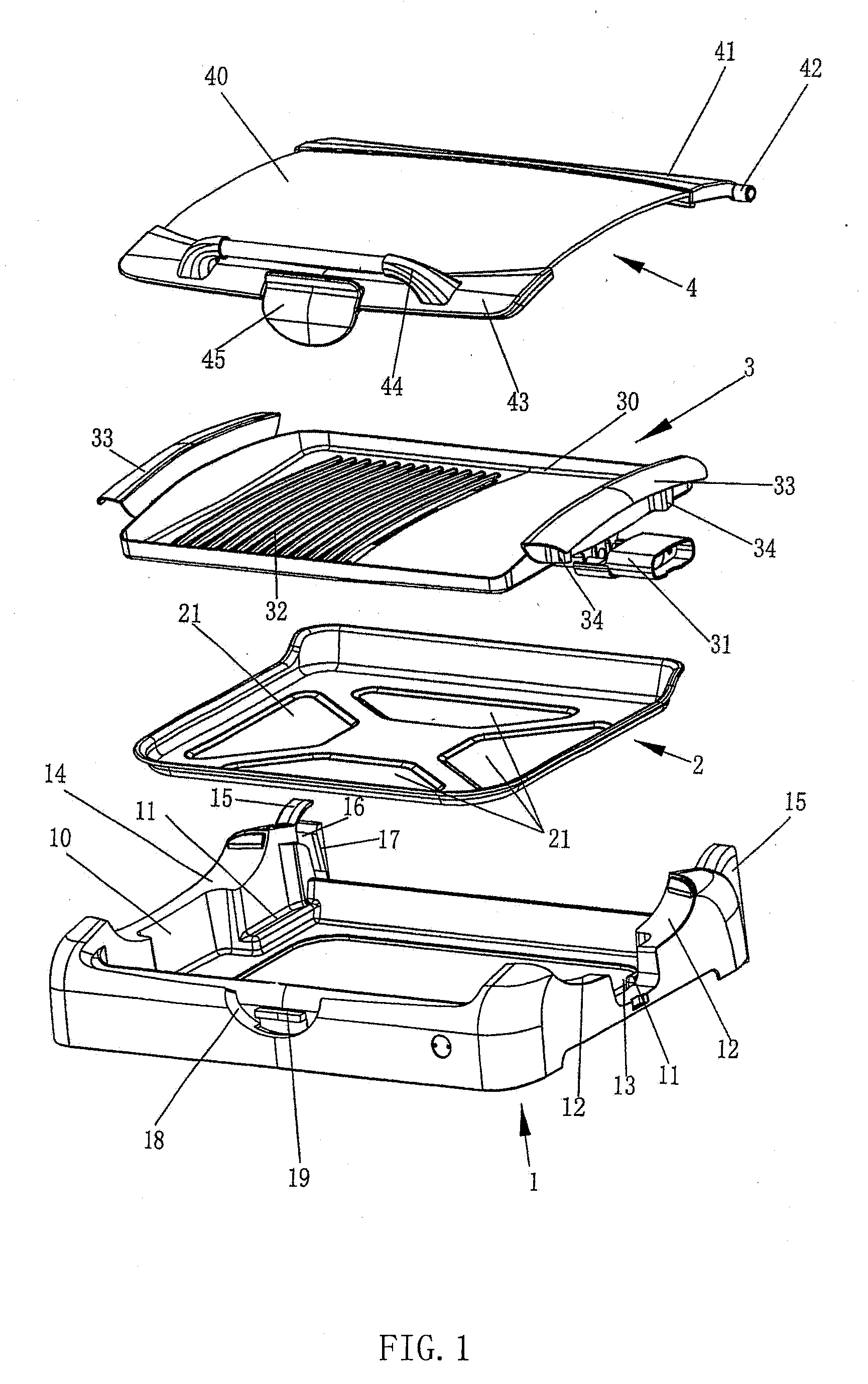
[0017]The exploded structure of the preferred embodiment of the lifting-cover type frying-roasting device as showed in FIG. 1. Said lifting-cover type frying-roasting device is composed of a bottom base 1, an oil storing plate 2, a electric heating frying-roasting plate 3 and an upper cover 4. Those four parts can be disassembled for cleaning, or may be assembled together for use as illustrated in FIG. 4 and FIG. 5.

[0018]There is a boss 11 respectively set at the opening of the top end of bottom base 1 and four corners of the bottom of the open space 10 inside said bottom base 1. And a curved groove 12 disposed at the top surface of the right side wall of said bottom base 1, the middle of groove 12 forms a small approximate rectangular groove 13 downward. A curved groove 14 is set at the top surface of the left side wall of said bottom base, wherein said groove 14 is opposite the groove 12 of the right side wall. There is a boss 15 respectively extending backward at two sides of the...


PUM


Abstract

A lifting-cover type frying-roasting device is provided. The frying-roasting device comprises a bottom base (1), an oil storing plate (2), an electric heating frying-roasting plate (3) and an upper cover (4). There is respectively a boss (15) extending backwards at two sides of the back end of the bottom base (1). A r-shaped orbit (16) whose opening is from its back end and extends toward its front lower part is respectively set in the inside of each boss (15). There is respectively a short jointed shaft (42) extending outward at the back end of two sides of the upper cover (4). Each short jointed shaft (42) is inserted in the corresponding r-shaped orbit (16) so that the hinging connection between them is formed. There is respectively a block wall (17) that extends from the back end to the inside of each boss (15). The height of two blocking walls (17) is lower than the opening of the r-shaped orbit (16). When the upper cover (4) is opened, the lower end of the back connecting member (41) of the upper cover (4) is blocked by the back end of the electric heating frying-roasting plate (3) and the upper end of the back connecting member (41) is blocked by two blocking walls (17) so that the upper cover remains sloped.

Description

TECHNICAL FIELD[0001]The present invention relates to an electric heating cooker, especially to an electrical frying-roasting device.BACKGROUND OF THE INVENTION[0002]The electrical frying-roasting device of the present technology, comprising a bottom base which has an open top, there is an electric heating frying-roasting plate disposed on the open top, and an upper cover for covering said frying-roasting plate. When frying or roasting the food, firstly turn on the power; secondly remove the upper cover and put the food on the frying-roast plate; then cover said upper cover on the frying-roast plate. When the food is about to be ready, remove the upper cover again, then flip the food on the frying-roasting plate; finally take the food out of the device when it is ready. During the process, it needs a space to accommodate said upper cover after removing it from the frying-roast plate, thus it causes inconvenience; furthermore, it may be difficult to clean the wall behind the electric...

Claims


Application Information

Patent Timeline
Patent Type & Authority Applications(United States)
IPC IPC(8): A47J37/06H05B3/68
CPCA47J37/0676A47J37/0623
Inventor LIN, JINGLIU, TACHI
Owner TSANN KUEN CHINA ENTERPRISE
Learn More