

Cable routing device
a routing device and cable technology, applied in the direction of electrical equipment, pipe supports, pipe/joints/fittings, etc., can solve the problems of high logistic cost, high installation cost, and high labor intensity of metal cable routing devices, so as to increase installation cost, easy and rapid transformation, and great weight
- Summary
- Abstract
- Description
- Claims
- Application Information
AI Technical Summary
Benefits of technology
Problems solved by technology
Method used
Image

Examples
Embodiment Construction
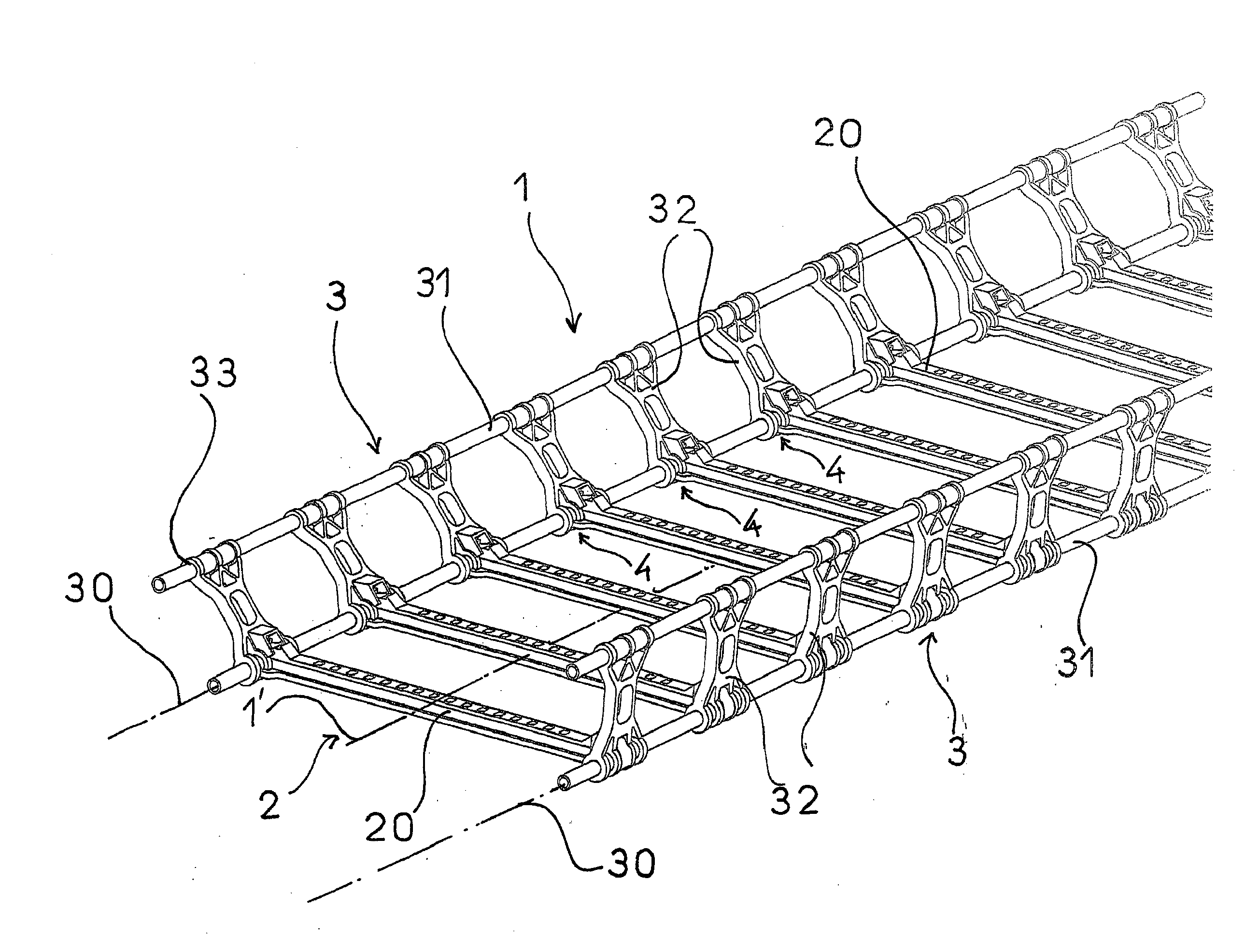
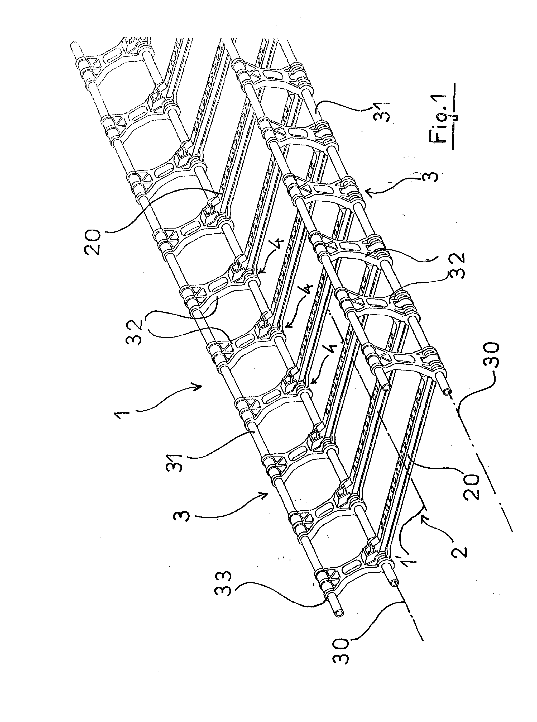
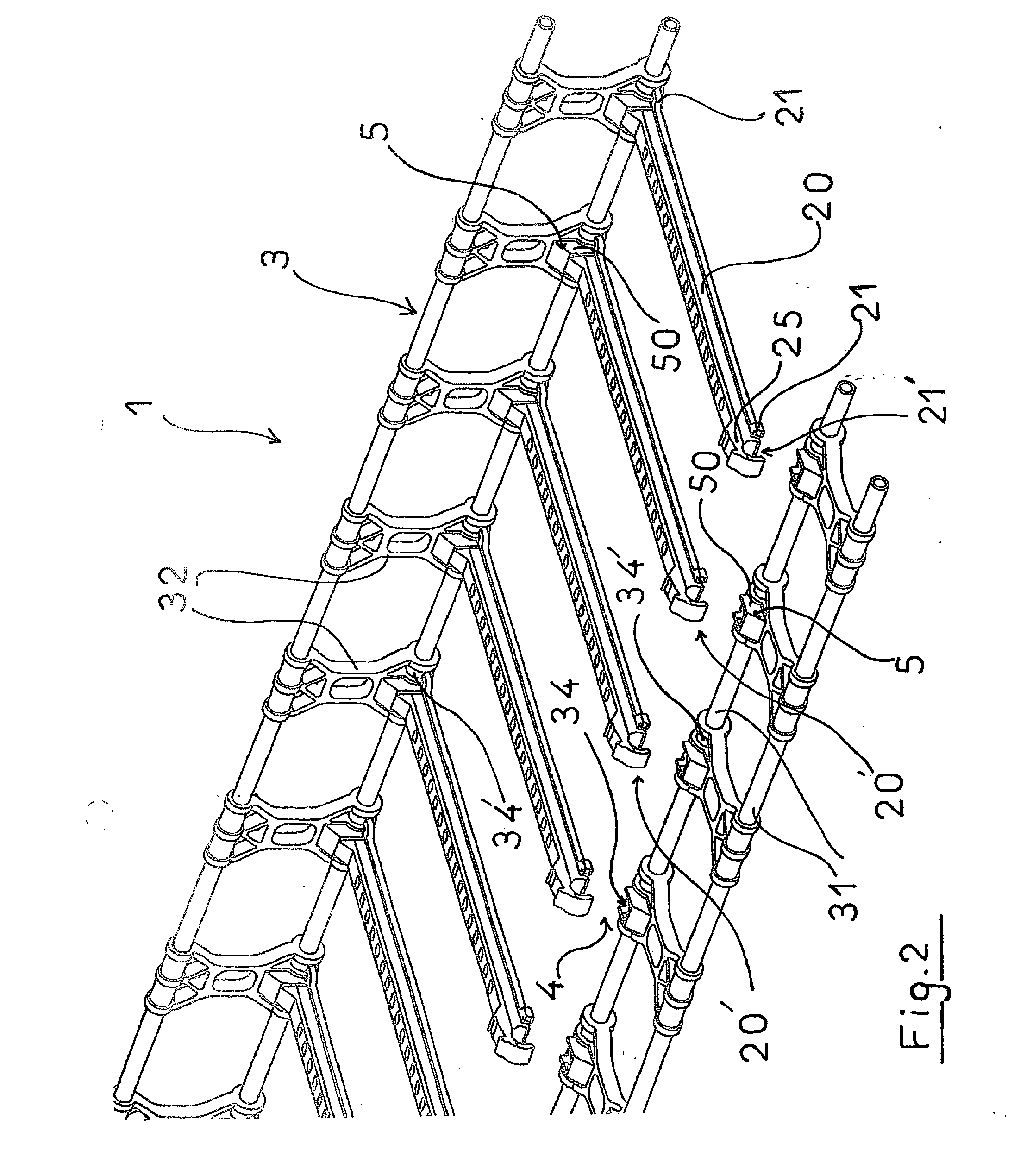
[0041]If reference is made to FIG. 1 and to FIG. 2, it may be seen that a cable routing device according to the present invention has a structure 1 with an elongated shape with a U-shaped cross-section and comprises a base 2 and two side posts 3, substantially made from a composite material or a reinforced plastic material.
[0042]The side posts 3 are pivotally mounted about an axis of rotation 30, parallel to the longitudinal axis 1′ of the cable route, defining the junction line between the base 2 and the side posts 3. In order to ensure pivoting of the side posts 3 relatively to the base 2, hinges 4 are firmly secured along the side walls of the base 2 and form a multiplicity of jointing points between the side posts 3 and the base 2.
[0043]It may be seen that the base 2 consists of a succession of bars 20, regularly spaced out, perpendicular to the longitudinal axis 1′ of the cable route 1 and to the axis of rotation 30, which bars 20 are firmly secured to the side posts 3 by their...
PUM
 Abstract
Description
Claims
Application Information