

Reduced voltage MEMS electrostatic actuation methods
a technology of electrostatic actuators and rf signals, applied in the direction of electrostatic generators/motors, electrostatic motors, electrical apparatus, etc., can solve the problem of being susceptible to rf signal induced self-actuation
- Summary
- Abstract
- Description
- Claims
- Application Information
AI Technical Summary
Benefits of technology
Problems solved by technology
Method used
Image

Examples
first embodiment
[0044]In a MEMS low voltage cantilever actuator the beam bending stiffness is decreased, without increasing beam length, by decreasing the beam width near the beam root to yield a device as shown in FIG. 4. In this design the bending stiffness is decreased, relative to the previously described straight uniform prismatic cantilever beam, by decreasing the width of the beam for a length (Lb<L) less than the total length of the actuator. The intent of narrowing the width of the beam near the root anchor is to decrease the bending stiffness of the beam while at the same time trying to minimize the decrease in the bending moment from the electrostatic force from the associated loss of electrostatic actuator area. The more distal the actuator area is from the beam root anchor, the more it contributes to the electrostatic bending moment due to the simple effect of the moment arm length and also to the gap geometry between stationary and movable actuator plates as the beam deflects. There i...
second embodiment
[0045]In a MEMS low voltage cantilever actuator the beam stiffness is decreased by the removal of beam material about the longitudinal center line near the beam root as shown in FIG. 5A. In this design the bending stiffness is decreased, relative to the previously described straight uniform prismatic cantilever beam, by decreasing the width of the beam for a length (Lb<L) less than the total length of the actuator. The intent of narrowing the width of the beam near the root anchor is to decrease the bending stiffness of the beam while at the same time trying to minimize the decrease in the bending moment from the electrostatic force from the associated loss of electrostatic actuator area. The more distal the actuator area is from the beam root anchor, the more it contributes to the electrostatic bending moment due to the simple effect of the moment arm length and also to the gap geometry between stationary and movable actuator plates as the beam deflects.
[0046]There is a design trad...
third embodiment
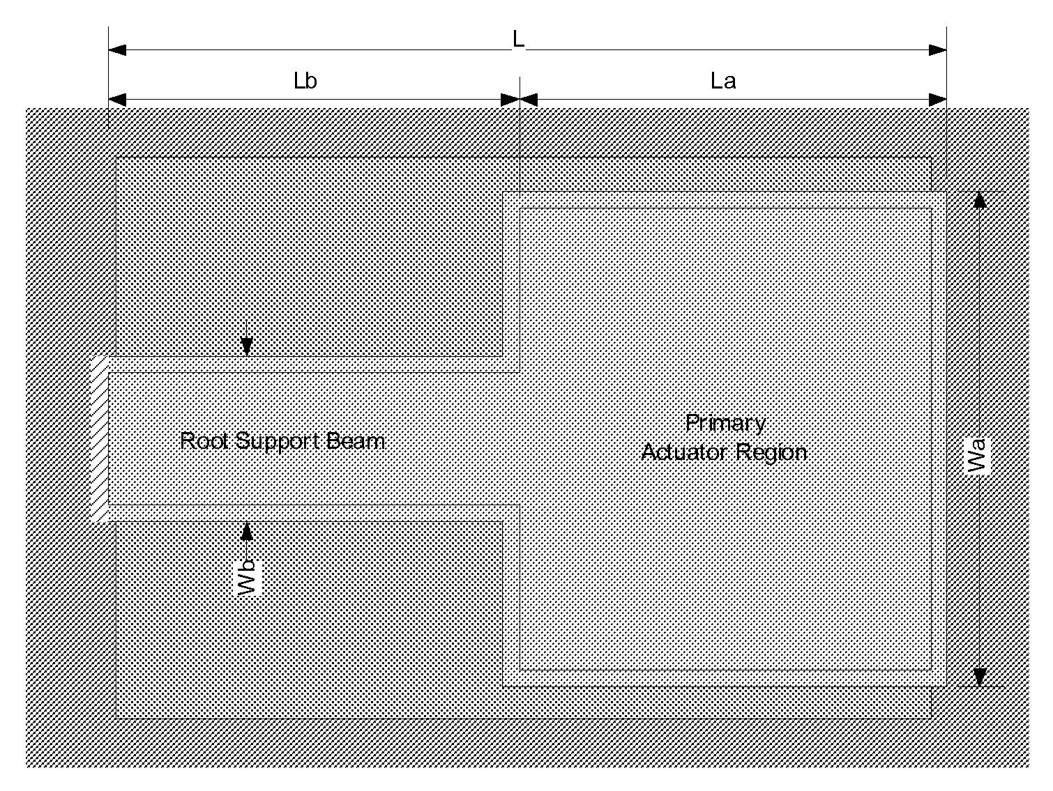
[0047]In a MEMS low voltage cantilever actuator the beam stiffness is decreased by the removal of beam material in a narrow slotting fashion such that bending stiffness is decreased in the beam root region similar to that of embodiment one, while minimizing the overall loss of electrostatic actuator area as shown in FIG. 7A. Alternatively, this design may be viewed as that shown in embodiment one with the addition of auxiliary actuation area. The actuation pull-in voltage for this design is primarily a function of the bending moment from the primary actuator defined by the actuation area (La*Wa) and the moment arm defined by the center of electrostatic pressure (Lb+˜La / 2), the stiffness of the root beam defined by its width Wb and length Lb, and by the area from the auxiliary actuation flaps defined by Wf and Lf. This embodiment of a MEMS cantilever electrostatic actuator may be used in applications for either a capacitive contact or ohmic (DC) contact switching device as depicted i...
PUM
 Abstract
Description
Claims
Application Information