Image forming apparatus

Inactive Publication Date: 2010-07-22
RICOH KK
View PDF1 Cites 22 Cited by
  • Summary
  • Abstract
  • Description
  • Claims
  • Application Information

AI Technical Summary

Benefits of technology

[0012]In an aspect of this disclosure, there is provided an image forming apparatus. The image forming apparatus includes a recording head including a nozzle surface having nozzles for jetting droplets of a liquid; a maintenance unit including a cap configured to cap the nozzle surface, a suction unit connected to the cap, and a wiping part configured to wipe the nozzle surface; a liquid container configured to contain the liquid to be supplied to the recording head; a pressure unit configured to pressurize the inside of a supply channel extending from the liquid container to the recording head at a pressurizing position along the supply channel; an opening

Problems solved by technology

Meanwhile, even if a cap is moved away from a nozzle surface after ink is suctioned and the negative pressure in the cap is decreased as described above, ink and bubbles adhering to the nozzle surface may be drawn into nozzle channels because of low

Method used


Image

  • Image forming apparatus
  • Image forming apparatus
  • Image forming apparatus

Examples


second embodiment

[0055]the present invention is described below with reference to a timing chart of FIG. 8.

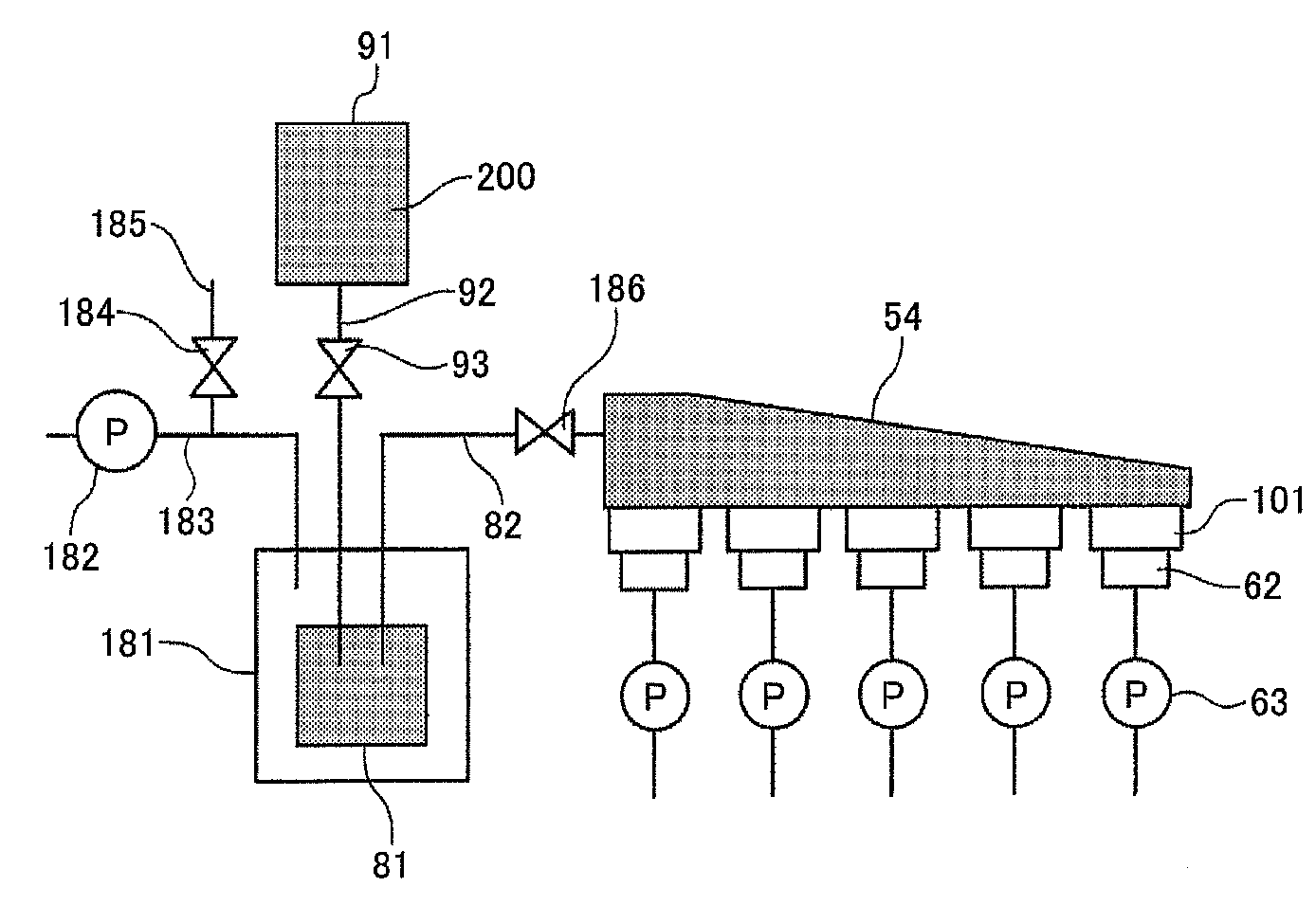
[0056]In this embodiment, the suction pump 63 is turned on at time t1 to start suctioning ink (bubbles and dried ink) from the nozzles 102 and at the same time, the pressure pump 182 is turned on to start applying pressure to the inside of the heads 101.

[0057]Performing a suction process and a pressurizing process concurrently as described above makes it possible to increase the flow velocity in the heads 101 and thereby to more effectively eject bubbles and dried ink from the nozzles.

third embodiment

[0058]A maintenance (cleaning) process according to the present invention is described below with reference to a flowchart of FIG. 9 and a timing chart of FIG. 10.

[0059]In the maintenance process of the third embodiment, the caps 62 are moved upward to contact the nozzle surfaces 104 of the heads 101, the supply channel shutoff valve 186 is closed (turned on) to close the supply channel 82, and the atmosphere opening valve 184 is closed (turned on) to close the atmosphere opening channel 185 for opening the air supply channel 183 to the atmosphere. Next, the pressure pump 182 is turned on to supply air into the pressure case 181 to increase the pressure in the pressure case 181. When the pressure in the pressure case 181 reaches a predetermined level, the pressure pump 182 is turned off.

[0060]Then, the suction pump 63 is turned on and the supply channel shutoff valve 186 is opened (turned off) to open the supply channel 82. As a result, the inside of the supply channel 82 is pressur...


PUM


Abstract

An image forming apparatus includes a suction unit; a pressure unit configured to pressurize the inside of a supply channel extending from a liquid container to a recording head at a pressurizing position along the supply channel; an opening and closing unit configured to open and close the supply channel at a position downstream of the pressurizing position; and a control unit configured to cap a nozzle surface with a cap and suction ink from nozzles with the suction unit, to move the cap away from the nozzle surface after pressurizing the inside of the supply channel with the pressure unit to a pressure greater than or equal to atmospheric pressure, to wipe the nozzle surface with a wiping part after closing the supply channel with the opening and closing unit, and to open the supply channel with the opening and closing unit after wiping the nozzle surface.

Description

BACKGROUND OF THE INVENTION[0001]1. Field of the Invention[0002]The present invention generally relates to an image forming apparatus. More particularly, a certain aspect of the present invention relates to an image forming apparatus including a recording head for jetting liquid droplets.[0003]2. Description of the Related Art[0004]A liquid-jet image forming apparatus such as an inkjet recording apparatus uses one or more recording heads for jetting ink droplets to form an image. A liquid-jet image forming apparatus is used, for example, for a printer, a facsimile machine, a copier, a plotter, and a multifunction copier having functions of them. Such a liquid-jet image forming apparatus jets liquid droplets from its recording heads onto paper being conveyed (“paper” in the present application is not limited to a sheet of paper but also refers to any medium, such as an OHP sheet, to which ink droplets or other liquid droplets can adhere, and may also be called a recording medium, rec...

Claims


Application Information

Patent Timeline
IPC IPC(8): B41J2/165
CPCB41J2/1652B41J2/16526B41J2/16532B41J2/16547B41J2/16588
Inventor NEMOTO, YUSUKETAKAHASHI, MASANORIHASEBE, DAISUKEASANO, YUKIHIRO
Owner RICOH KK
Why Eureka
Try Eureka