Data capture system

a data capture and data technology, applied in the field of data capture systems, can solve the problems of less than desired image resolution, captured aerial images may not be well-suited for adaption to three-dimensional models,

Active Publication Date: 2010-07-22
MICROSOFT TECH LICENSING LLC
View PDF7 Cites 31 Cited by
  • Summary
  • Abstract
  • Description
  • Claims
  • Application Information

AI Technical Summary

Problems solved by technology

Because these images are aerial images, however, the resolution of the images is less than desired.
Mor

Method used


Image

  • Data capture system
  • Data capture system
  • Data capture system

Examples


Embodiment Construction

[0025]Various technologies pertaining to capturing data from cameras and sensors will now be described with reference to the drawings, where like reference numerals represent like elements throughout. In addition, several functional block diagrams of example systems are illustrated and described herein for purposes of explanation; however, it is to be understood that functionality that is described as being carried out by certain system components may be performed by multiple components. Similarly, for instance, a component may be configured to perform functionality that is described as being carried out by multiple components.

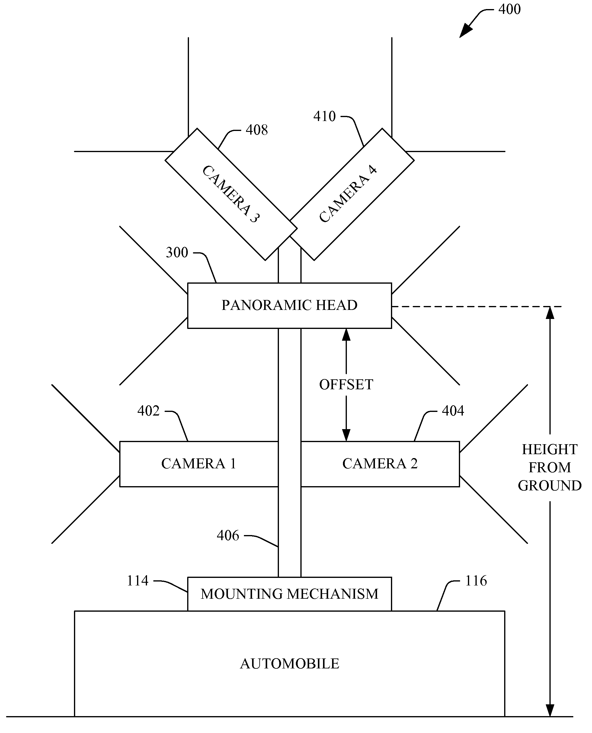
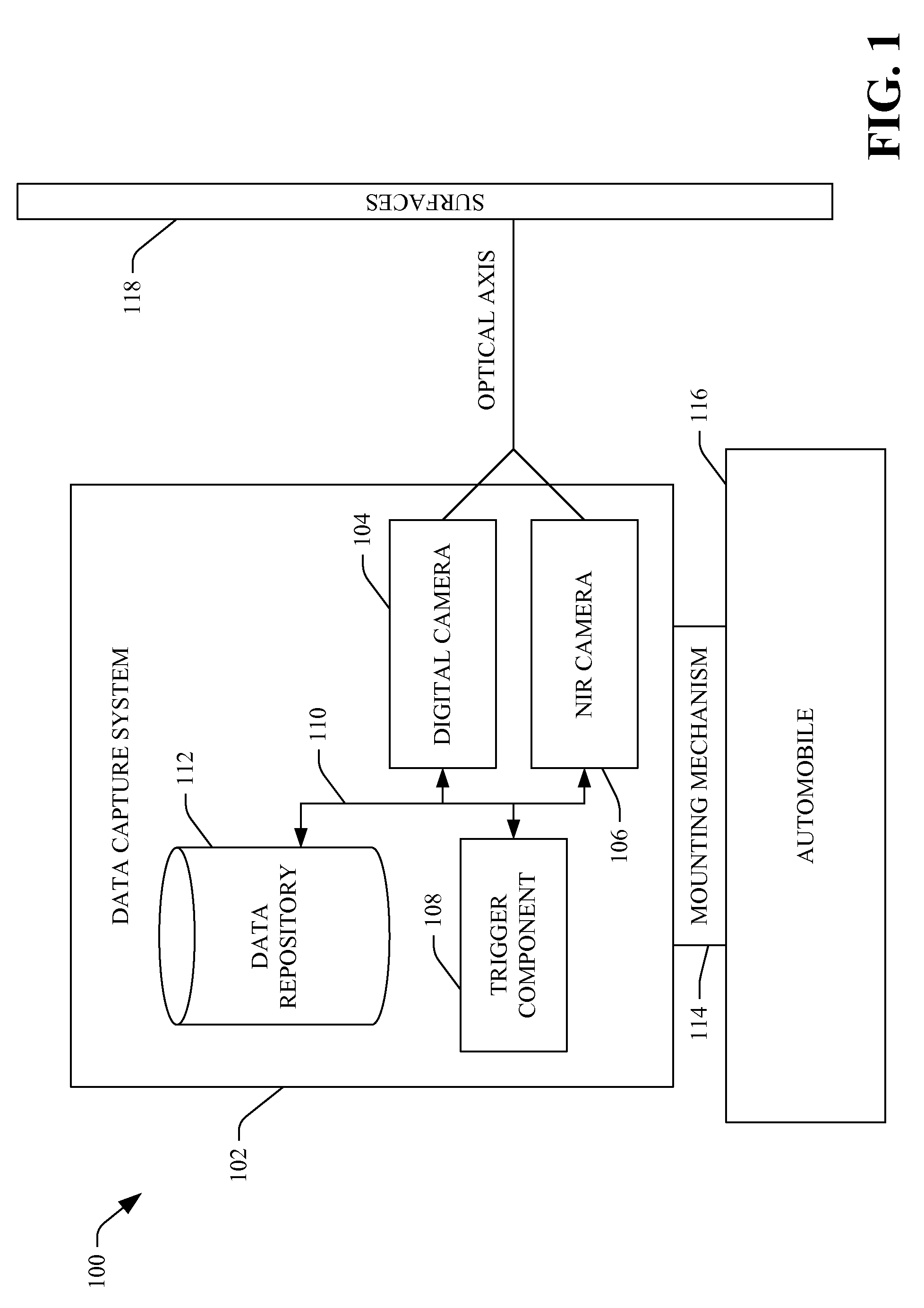
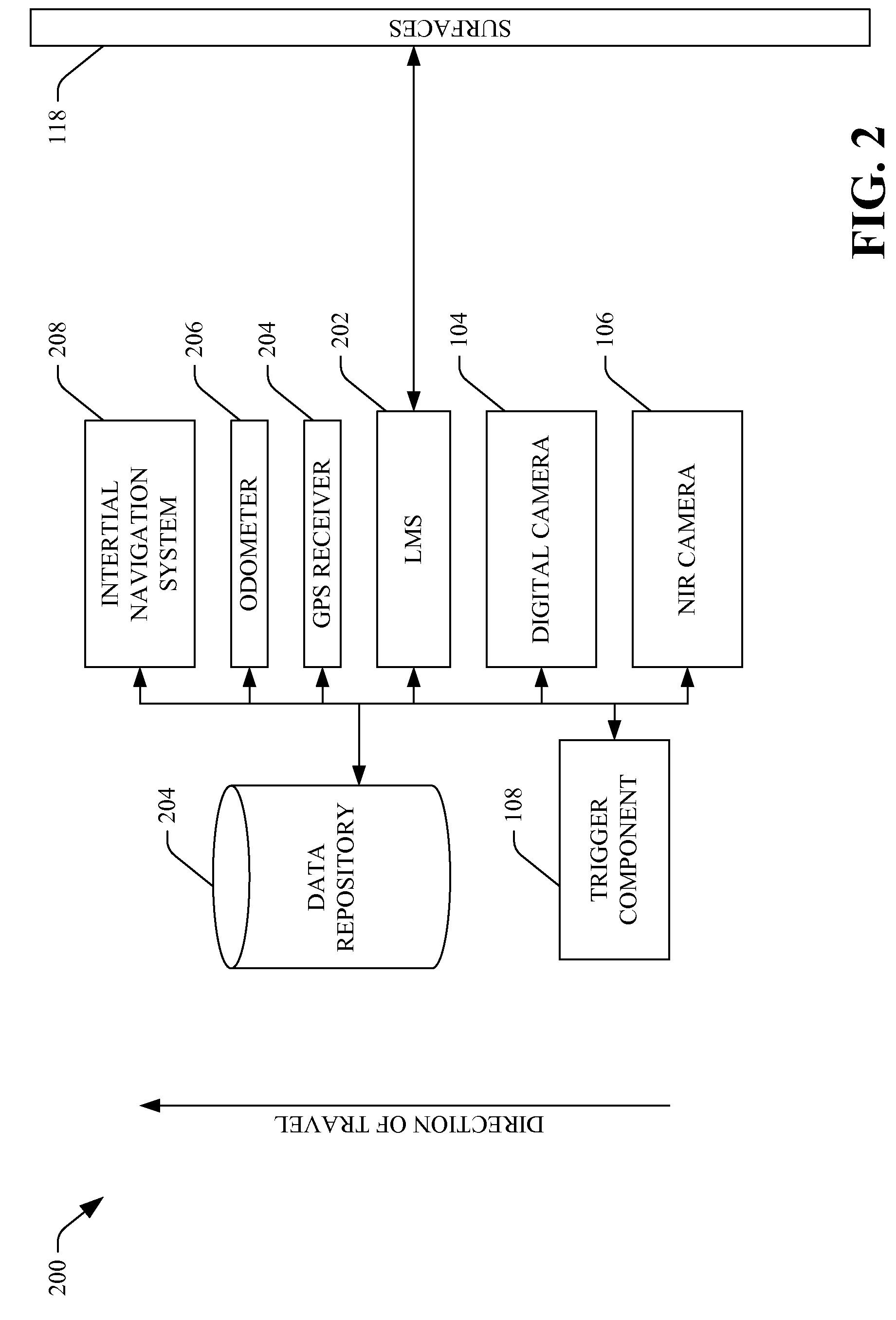
[0026]With reference to FIG. 1, an example system 100 that facilitates capturing images is illustrated. The system 100 includes a data capture system 102, which can include a digital camera 104 and a near-infrared (NIR) camera 106. The digital camera 104 and the NIR camera 106 can be positioned proximate to one another such that the field of view of the digita...


PUM


Abstract

A system that facilitates collecting data is described herein. The system includes a digital camera that is configured to capture images in a visible light spectrum and a near-infrared camera that is configured to capture near infrared images, wherein a field of view of the digital camera and the field of view of the near-infrared camera are substantially similar. The system further includes a trigger component that is configured to cause the digital camera and the near-infrared camera to capture images at a substantially similar point in time, and also includes a mounting mechanism that facilitates mounting the digital camera and the near-infrared camera to an automobile.

Description

BACKGROUND[0001]Functionality of conventional mapping applications that are accessible by way of the Internet has substantially increased over time. For instance, a user can access a mapping application and be provided with an overhead view of one or more streets. Still further, the user may provide an initial location (e.g., street address) and a destination, and the mapping application can provide the user with detailed directions pertaining to travelling between the initial location and the destination.[0002]Mapping applications have further developed such that an individual can view aerial images of a particular region. For instance, if a user enters a particular location (e.g., address, business name, . . . ), the user can be provided with aerial images pertaining to such entered location. These images may then be subjected to a zooming function, such that the user can be provided with a relatively close aerial view of the entered location. Furthermore, driving directions may b...

Claims


Application Information

Patent Timeline
IPC IPC(8): H04N7/00H04N5/33G08G1/123H04N7/18
CPCG01S19/14G01S19/49H04N5/247H04N5/23238H04N5/33H04N7/181B60R1/00B60R2300/105B60R2300/108B60R2300/303H04N23/90H04N23/698
Inventor KROEPFL, MICHAELGRUBER, MICHAELPONTICELLI, MARTIN JOSEFLAWLER, STEPHENBAUER, JOACHIMLEBERL, FRANZ W.KARNER, KONRADCOSIC, ZANINHEGENBARTH, HANNESKIMCHI, GURCURLANDER, JOHN CHARLES
Owner MICROSOFT TECH LICENSING LLC
Why Eureka
Try Eureka