Eureka AIR delivers breakthrough ideas for toughest innovation challenges, trusted by R&D personnel around the world.

Thermoplastic mandrels for composite fabrication

a technology of thermoplastic mandrels and composite fabrication, which is applied in the direction of process and machine control, instruments, mechanical control devices, etc., can solve the problems of metal mandrels damaging the finished part, changing expansion properties, and complications in reaching a level

Inactive Publication Date: 2010-07-29
AIRTECH INT INC
View PDF49 Cites 71 Cited by
  • Summary
  • Abstract
  • Description
  • Claims
  • Application Information

AI Technical Summary

Benefits of technology

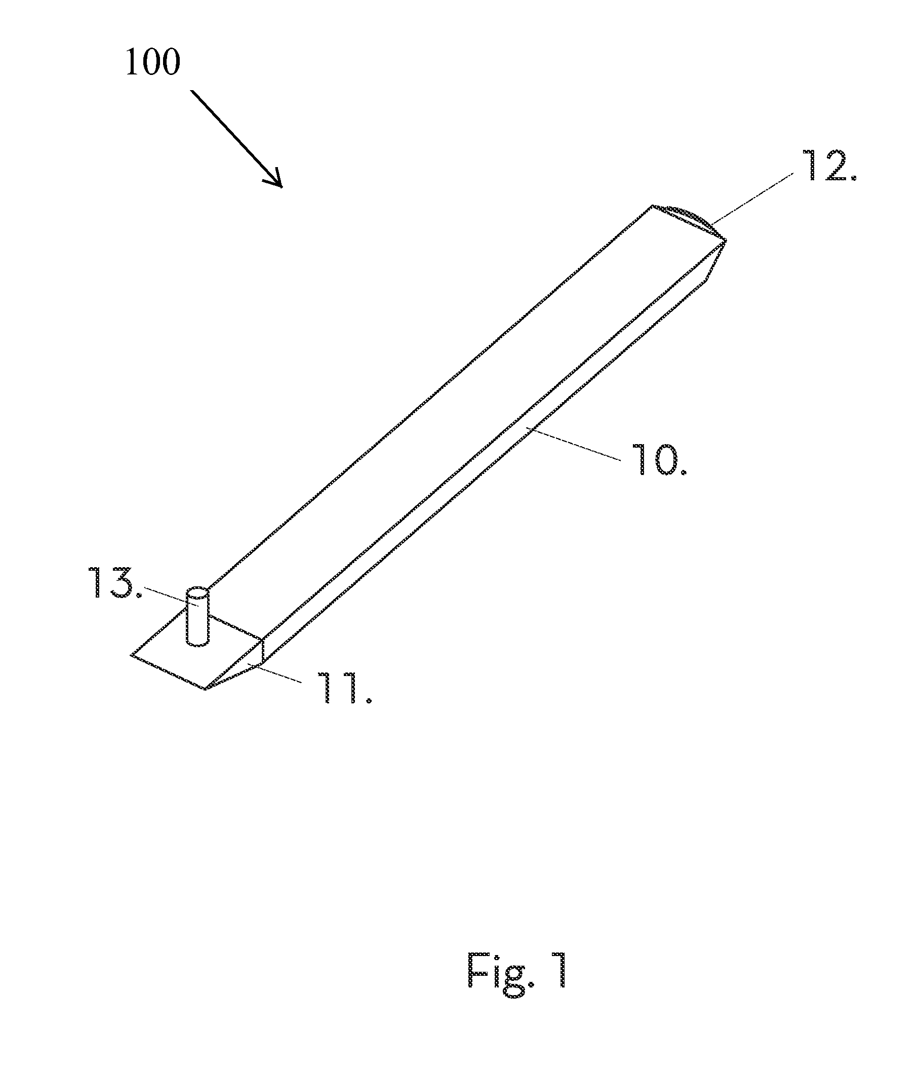
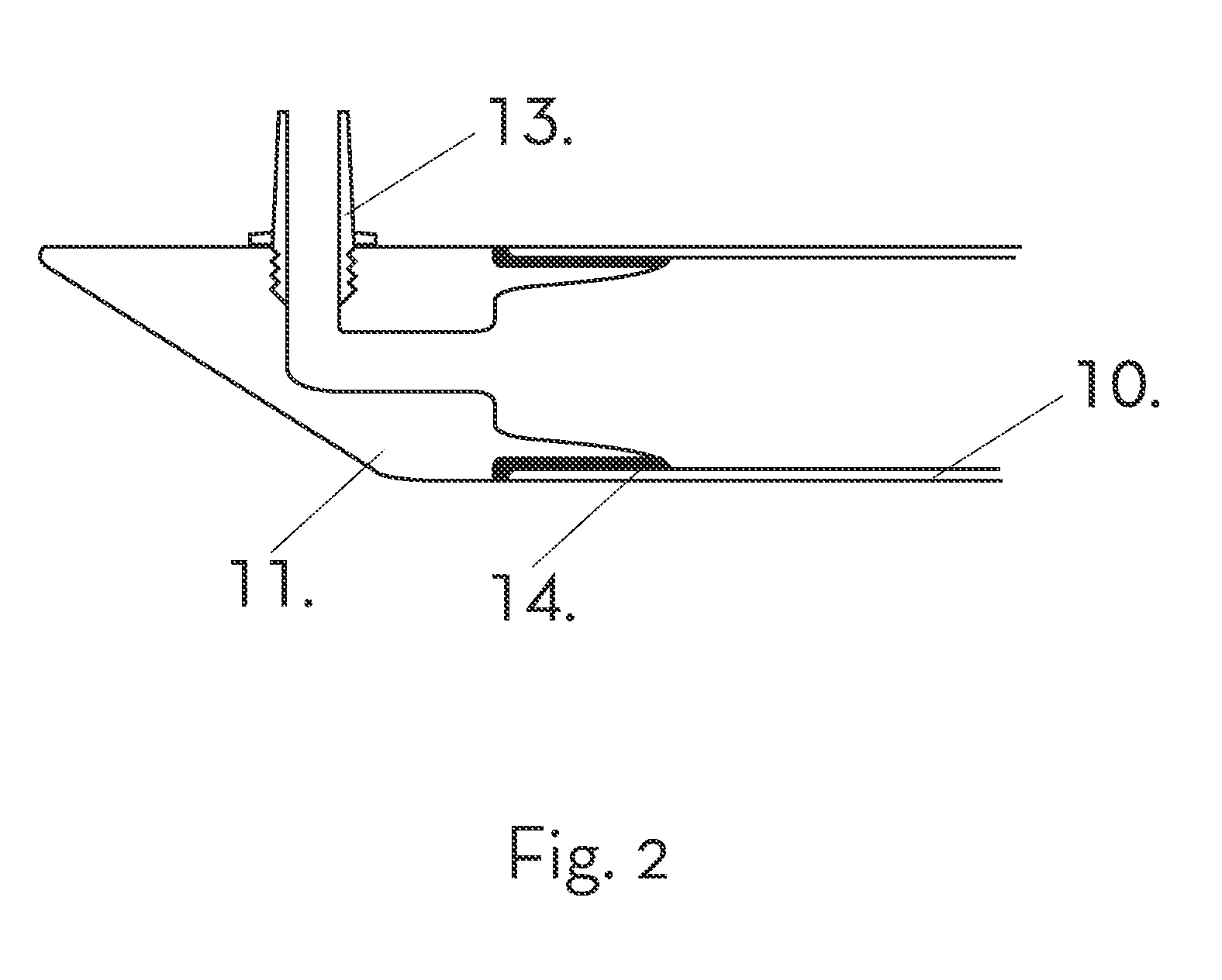
The patent describes a mandrel assembly that has a hollow portion made of thermoplastic material that can be extruded. This hollow portion has closed ends and a vent tube connected to one of the closed ends. The vent tube allows air to flow between the interior of the mandrel and the outside. The technical effect of this invention is that it provides a way to control the air flow in a mandrel assembly, which can improve the manufacturing process of certain products.

Problems solved by technology

Mandrels formed with metal or metal alloys have been used, but depending on the part configuration, coefficient of thermal expansion, and ease of extraction, the metal mandrels can damage the finished part.
With metallic mandrels there can be complications in reaching a level of quality for a non destructing inspection (NDI result) needed for composite structures in certain structures.
These solid mandrels have drawbacks due to the difficulty of predicting actual thermal expansion in use, changing expansion properties over multiple fabrication cycles, and in some cases difficulty in extraction of the mandrel from the finished part.
With silicone mandrels, there is a possibility of contamination that can have an adverse impact on secondary bonding and painting of the composite part.
However, a drawback of bonded Teflon is the presence of at least one split line in the Teflon.
The thin line of exposed rubber at the split line of the molds can be weakened by the resins during the composite cure process.
This can significantly shorten the usable life of the rubber mandrel.
The thin line of exposed rubber can also be a starting point for leaks in the mandrel, causing other defects.
Due to high cost of labor needed for hand laid-up mandrels, these mandrels can be costly to use during the production process.

Method used


Image

  • Thermoplastic mandrels for composite fabrication
  • Thermoplastic mandrels for composite fabrication
  • Thermoplastic mandrels for composite fabrication

Examples


Embodiment Construction

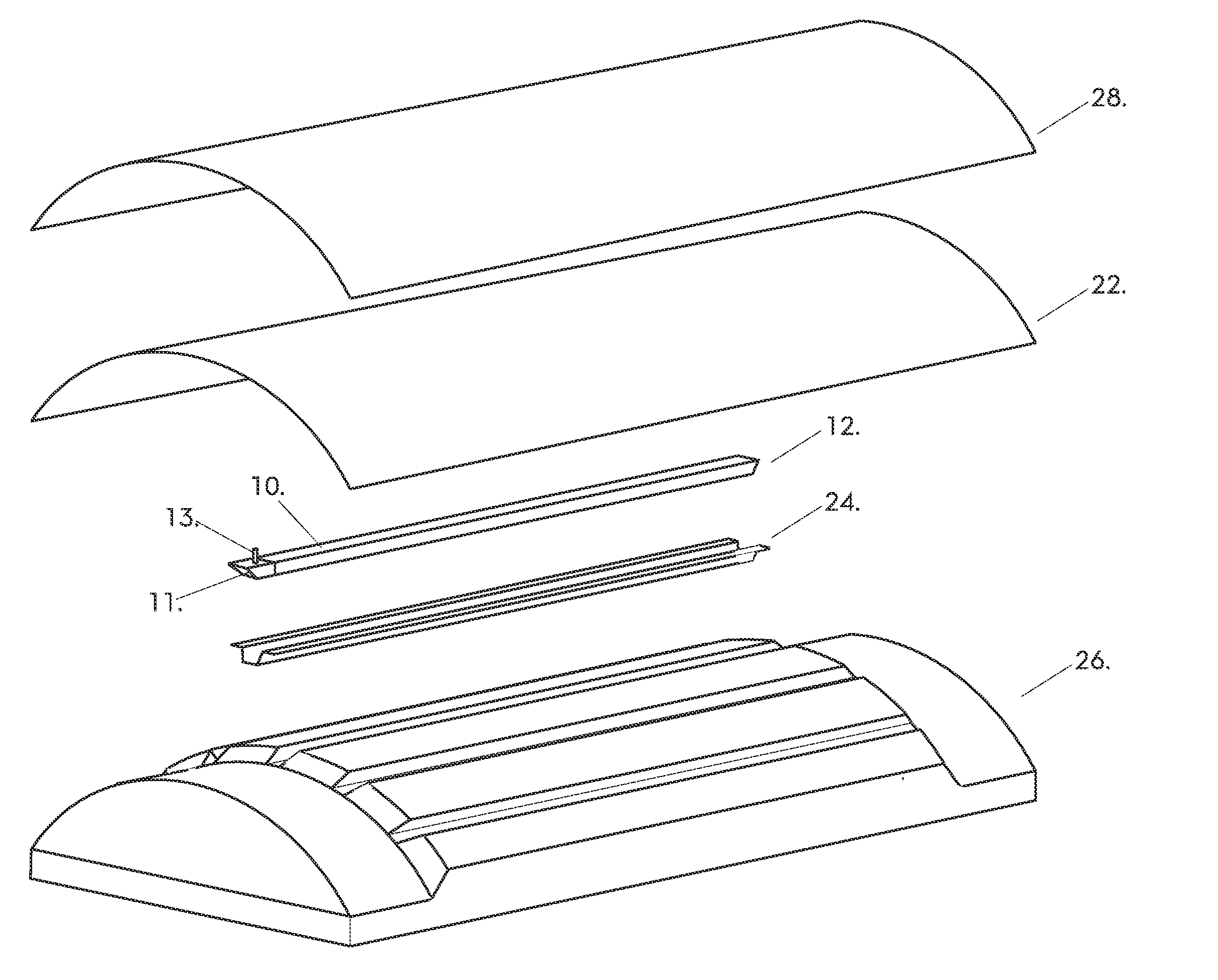
[0020]The new method utilizes a thermoplastic extrusion for the body of the mandrel. This method enables a seamless mandrel in any constant section, of any length. The mandrels can be monolayer or multilayer. For most applications the strength, vacuum integrity and release characteristics of one layer of thermoplastic material is sufficient, and polymethylpentene blends can be used as the thermoplastic material. However, in certain applications other polymers may be used, in monolayer and / or multilayer combinations. If needed, multilayer extrusions may provide added strength, vacuum integrity, chemical resistance and release characteristics. As the mandrels are extruded rather than molded, there are no constraints due to the length of the mold, oven size or press limitations. For example, oven sizes or press limitation may not be able to create panels of up to 18 meters long. However, the extruded mandrels are not limited in size and can be up to and greater than 18 meters long. The...


PUM

PropertyMeasurementUnit
surface tensionaaaaaaaaaa
temperatureaaaaaaaaaa
sizesaaaaaaaaaa

Abstract

A mandrel assembly that includes an elongated hollow structure comprising a thermoplastic material that is extrudable having a first end and a second end. A first end cap attached to the first end. A vent tube attached to the first end cap, the vent tube extending from the first end cap. A second end cap attached to the second end. The mandrel assembly adapted to shape and form a composite structure in or outside an autoclave.

Description

CROSS-REFERENCE TO RELATED PATENT APPLICATIONS[0001]This application claims priority from Provisional Application No. 61 / 144,942, filed Jan. 15, 2009, incorporated herein by reference in its entirety.FIELD OF THE DISCLOSURE[0002]Embodiments of the present invention relate to the process for fabricating a mandrel used in the fabrication of composite articles by fabrication techniques such as, but not limited to, fiber placement, tape laying, hand lay-up, resin infusion and resin transfer molding processes cured both in and out of an autoclave.BACKGROUND OF THE DISCLOSURE[0003]Composite structures can be formed into various shapes by using a variety of materials. Mandrels may be used to shape composite structures. Composite structures can be designed and fabricated in various shapes, such as but not limited to, “hat” sections, “T” or “J” shaped stiffeners or “I” beams as part of a design. Each of the above shapes can be co-cured or co-bonded. Secondary tooling can be used to locate, s...

Claims


Application Information

Patent Timeline
Patent Type & Authority Applications(United States)
IPC IPC(8): B32B37/10B29C47/06B29C48/09B29C48/12B29C48/15B29C48/21
CPCB29C33/10B29C33/3842B29C33/40B29C70/446B29L2022/00B29C48/21B29L2031/757B29C48/15B29C48/09B29C48/12B29C48/0016B29L2031/003
Inventor JACKSON, AUBREY G.MALIGIE, JOHN D.
Owner AIRTECH INT INC
Why Eureka
Eureka Blog
Learn More