
Non-reciprocal circuit device

a circuit device and non-reciprocal technology, applied in waveguide devices, basic electric elements, electrical equipment, etc., can solve the problems of greatly impaired insertion loss and insertion loss reduction, and achieve the effect of improving insertion loss and improving insertion loss

Inactive Publication Date: 2010-07-29
MURATA MFG CO LTD
View PDF1 Cites 0 Cited by
  • Summary
  • Abstract
  • Description
  • Claims
  • Application Information

AI Technical Summary

Benefits of technology

The present invention provides a nonreciprocal circuit device with improved insertion loss. The device includes a ferrite and permanent magnets that apply a direct current magnetic field to the ferrite without affecting its profile. The device also includes a first and second center electrode that are insulated from each other and intersect with the ferrite. The permanent magnets are positioned to oppose the principal surfaces of the ferrite, and the portions of the magnets opposing the relay electrodes are thicker than the other portions. This results in a large magnetic flux at the ends of the ferrite, which even when leakage flux occurs, produces a direct current magnetic field with a substantially equal magnetic flux density to the center portion of the ferrite. Overall, the nonreciprocal circuit device provides a direct current magnetic field with an even density that improves insertion loss.

Problems solved by technology

This arrangement has a problem in that the density of magnetic flux applied to the principal surfaces of the ferrite 32 becomes uneven, and thus the insertion loss decreases.
In particular, a reduction in profile is greatly impaired.

Method used


Image

  • Non-reciprocal circuit device
  • Non-reciprocal circuit device
  • Non-reciprocal circuit device

Examples


Embodiment Construction

[0028]Preferred embodiments of a nonreciprocal circuit device according to the present invention will now be described with reference to the attached drawings.

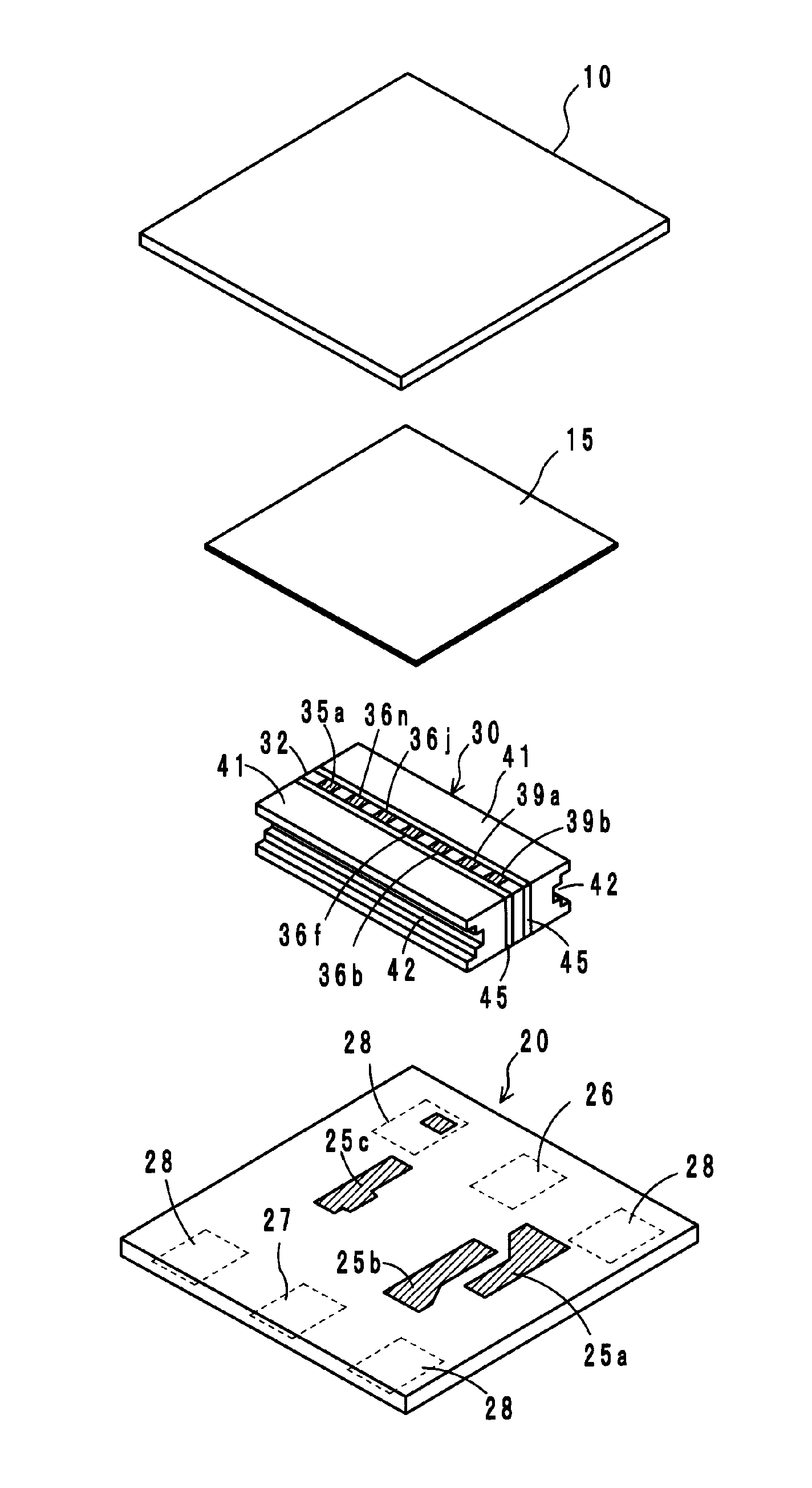
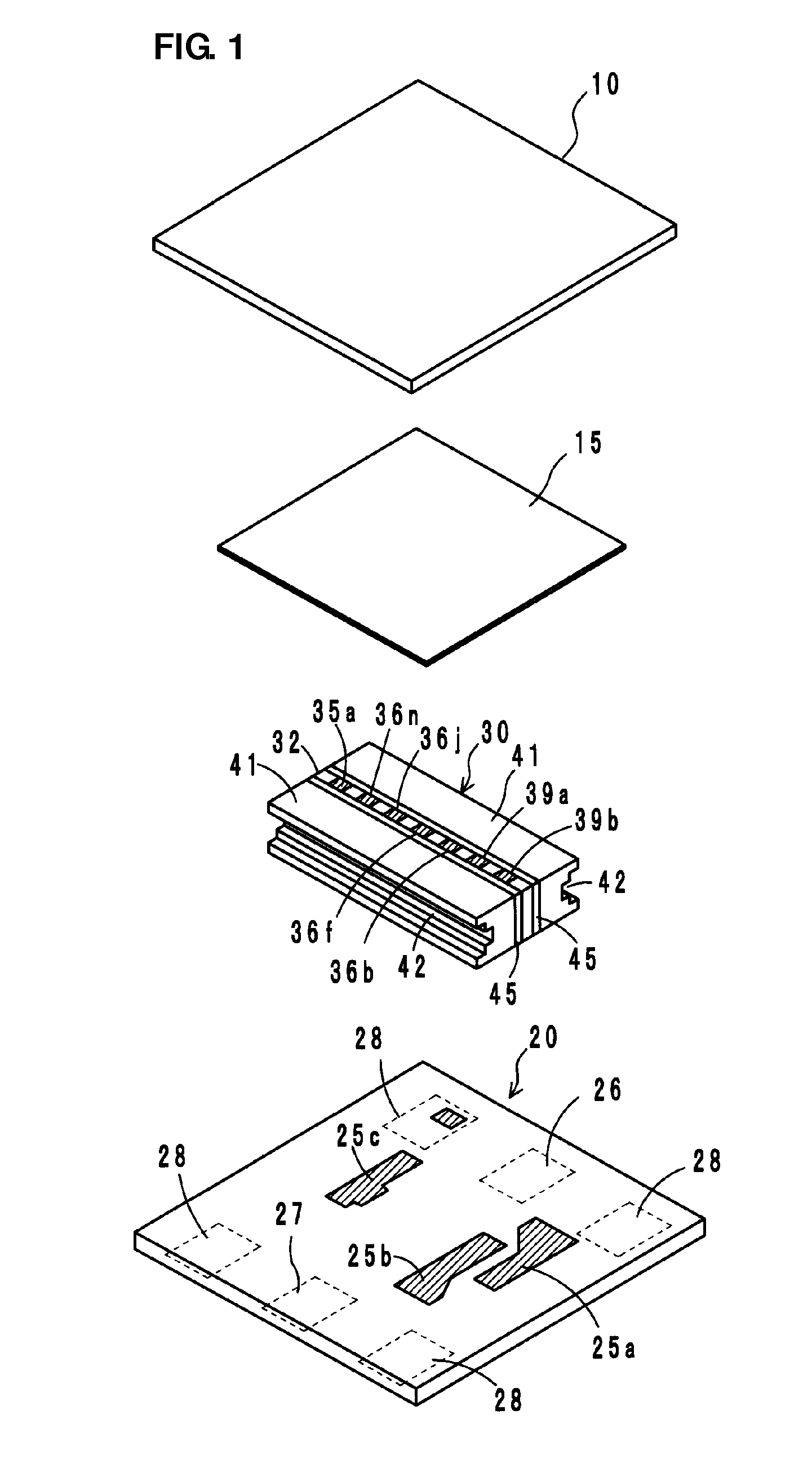
[0029]An exploded perspective view of a two-port isolator according to a preferred embodiment of the nonreciprocal circuit device according to the present invention is shown in FIG. 1. The two-port isolator is a lumped constant isolator and preferably includes a planar yoke 10, a circuit board 20, and a ferrite-magnet assembly 30 that includes a ferrite 32 and a pair of permanent magnets 41. In FIG. 1, shaded portions indicate electrical conductors.

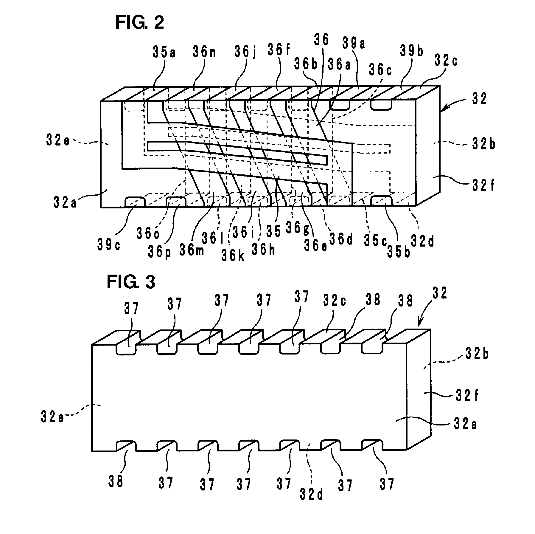
[0030]In the ferrite 32, a first center electrode 35 and a second center electrode 36 electrically insulated from each other are provided on front and back principal surfaces 32a and 32b, as shown in FIG. 2. The ferrite 32 preferably has a rectangular parallelepiped shape that includes the first principal surface 32a and the second principal surface 32b parallel or substantially par...


PUM


Abstract

A nonreciprocal circuit device has a structure that allows a direct current magnetic field having an even density to be applied to a necessary portion of a ferrite without impairing a reduction in profile so as to improve insertion loss. The nonreciprocal circuit device, for example, a two-port isolator, includes permanent magnets, a ferrite to which a direct current magnetic field is applied by the permanent magnets, and a first center electrode and a second center electrode that are disposed on the ferrite. The permanent magnets are disposed so as to oppose principal surfaces of the ferrite. Portions of each of the permanent magnets opposing relay electrodes on top and bottom surfaces are preferably thicker than other portions thereof.

Description

BACKGROUND OF THE INVENTION[0001]1. Field of the Invention[0002]The present invention relates to nonreciprocal circuit devices, and in particular, relates to a nonreciprocal circuit device such as an isolator and a circulator used in a microwave band.[0003]2. Description of the Related Art[0004]Conventional nonreciprocal circuit devices such as isolators and circulators have had characteristics that transmit signals only in a predetermined specific direction and do not transmit signals in the opposite direction. For example, isolators are used in transmitter circuits in mobile communication equipment such as car phones and cellular phones, using the characteristics described above.[0005]A nonreciprocal circuit device of such a type includes an assembly that includes a ferrite in which center electrodes are provided and permanent magnets that apply a direct current magnetic field to the ferrite. An improvement in electric characteristics, a reduction in size, especially, a reduction ...

Claims


Application Information

Patent Timeline
Patent Type & Authority Applications(United States)
IPC IPC(8): H01P1/36H01P1/32
CPCH01P1/387
Inventor KITAMORI, NOBUMASAHASEGAWA, TAKASHI
Owner MURATA MFG CO LTD
Learn More