
Communication system with broadband antenna

Active Publication Date: 2010-07-29
ASTRONICS AEROSAT CORP
View PDF22 Cites 87 Cited by
  • Summary
  • Abstract
  • Description
  • Claims
  • Application Information

AI Technical Summary

Benefits of technology

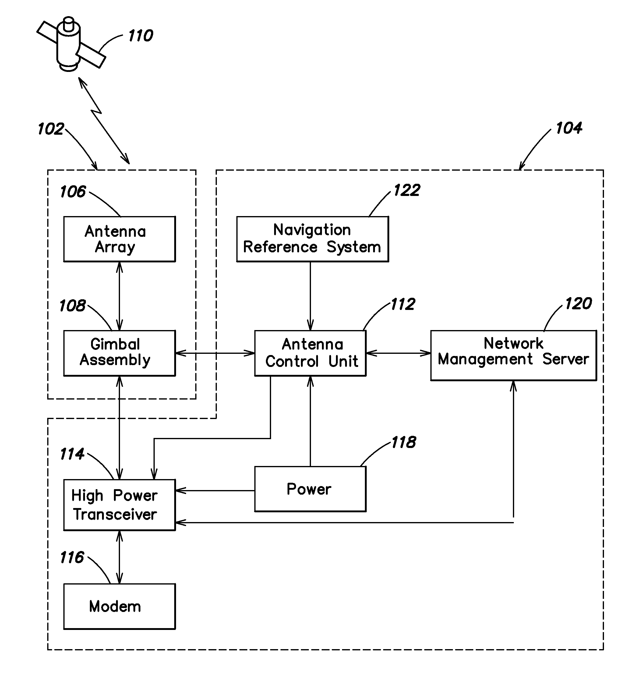
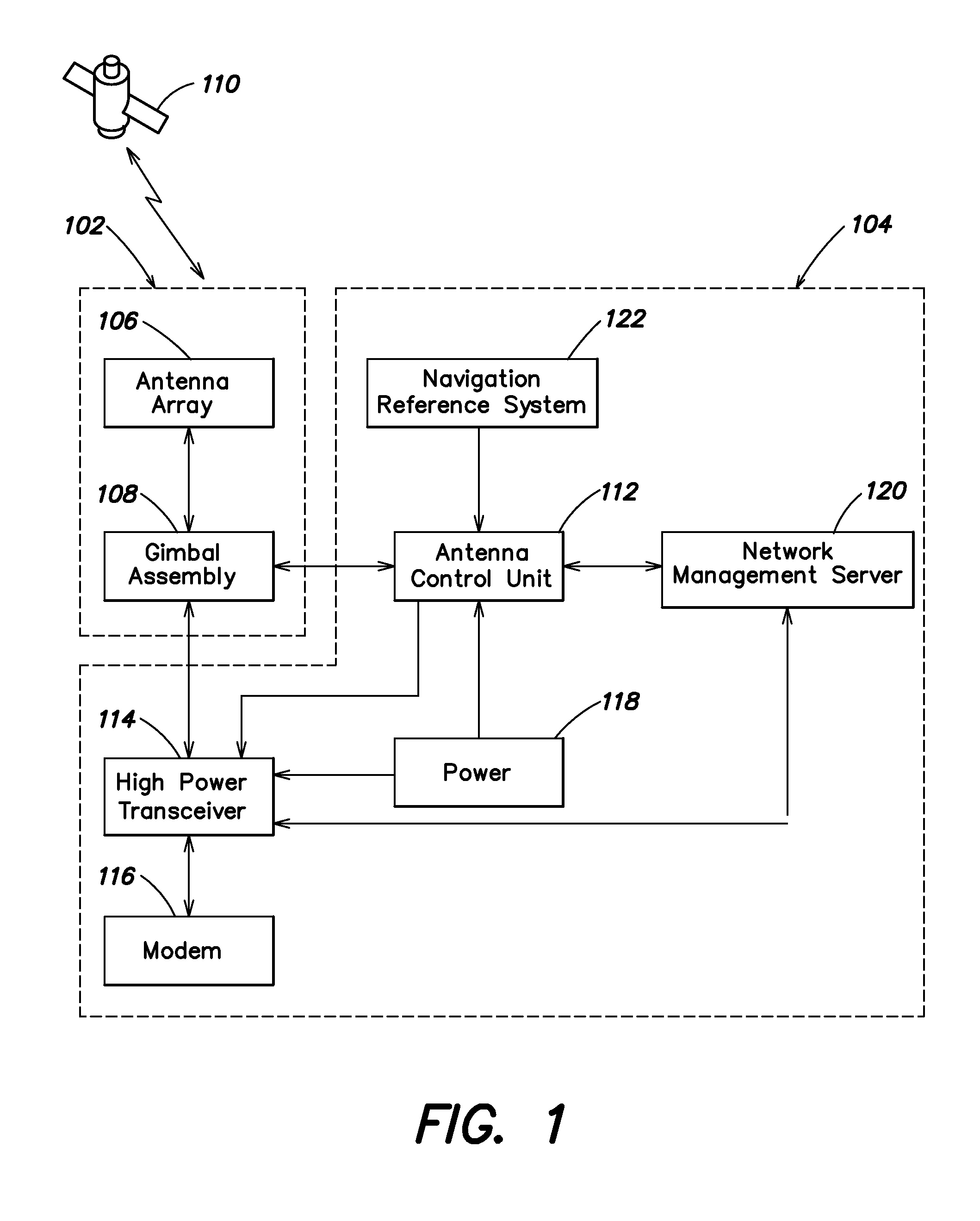
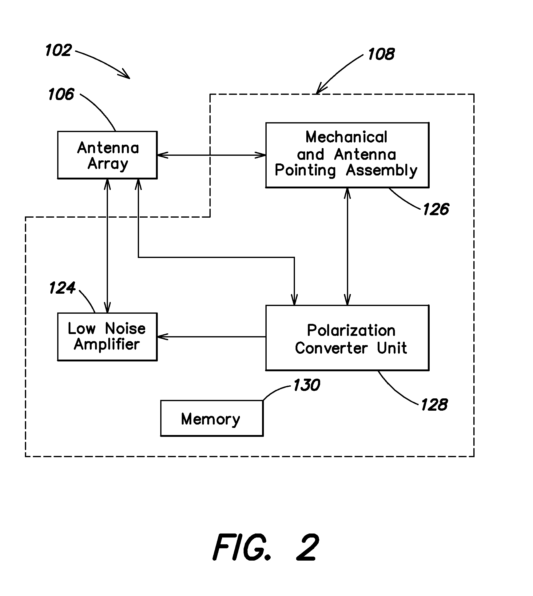
[0008]Aspects and embodiments are directed to a communications system including an antenna array and electronics assembly that may be mounted on and in a vehicle. The communication system may generally comprise an external subassembly that is mounted on an exterior surface of the vehicle, and an internal subassembly that is located within the vehicle, the external and internal subassemblies being communicatively coupled to one another. As discussed below, the external subassembly may comprise the antenna array as well as mounting equipment and steering actuators to move the antenna array in azimuth, elevation and polarization (for example, to track a satellite or other signal source). The internal subassembly may comprise most of the electronics associated with the communication system. Locating the internal subassembly within the vehicle may facilitate access to the electronics, and may protect the electronics from the environment exterior to the vehicle, as discussed in further detail below. Embodiments of the communication system provide numerous advantages over prior art systems, including being of relatively small size and weight (which may be particularly advantageous for a system mounted on an aircraft), and having excellent, broadband RF performance, as discussed further below.

Problems solved by technology

However, these systems may suffer from limited field of view or low efficiency that limit their ability to receive satellite signals.
In particular, these conventional systems may lack the performance required to receive satellite signals where either the signal strength is low or noise is high, for example, signals from low elevation satellites.
In addition, many conventional systems do not include any or sufficient polarization correction and therefore cross-polarized signal noise may interfere with the desired signal, preventing the system from properly receiving the desired signal.
Further, locating such systems on a fuselage of an aircraft for transmission or reception of signals poses a number of issues that must be addressed for such systems.

Method used


Image

  • Communication system with broadband antenna
  • Communication system with broadband antenna
  • Communication system with broadband antenna

Examples


Embodiment Construction

[0115]Aspects and embodiments are directed to a communication system including an antenna array and electronics subassembly that may be mounted on and in a vehicle. The communication system may generally comprise an external subassembly that is mounted on an exterior surface of the vehicle, and an internal subassembly that is located within the vehicle, the external and internal subassemblies being communicatively coupled to one another. As discussed below, the external subassembly may comprise the antenna array as well as mounting equipment and steering actuators to move the antenna array in azimuth, elevation and polarization (for example, to track a satellite or other signal source). The internal subassembly may comprise most of the electronics associated with the communication system. Locating the internal subassembly within the vehicle may facilitate access to the electronics, and may protect the electronics from the environment exterior to the vehicle, as discussed in further ...


PUM


Abstract

A communications system including an antenna array and electronics assembly that may be mounted on and in a vehicle. The communication system may generally comprise an external subassembly that is mounted on an exterior surface of the vehicle, and an internal subassembly that is located within the vehicle, the external and internal subassemblies being communicatively coupled to one another. The external subassembly may comprise the antenna array as well as mounting equipment and steering actuators to move the antenna array in azimuth, elevation and polarization (for example, to track a satellite or other signal source). The internal subassembly may comprise most of the electronics associated with the communication system.

Description

CROSS-REFERENCE TO RELATED APPLICATIONS[0001]This application claims priority under 35 U.S.C. §119(e) to U.S. Provisional Application No. 61 / 107,606, entitled “Communication System with Broadband Antenna” filed Oct. 22, 2008 and to U.S. Provisional Application No. 61 / 108,237 entitled “Communication System with Broadband Antenna” filed Oct. 24, 2008. This application is a continuation-in-part of, and claims priority to, PCT Application No. PCT / US08 / 76216 entitled “Communication System with Broadband Antenna” filed Sep. 12, 2008, which claims priority to U.S. Provisional Application No. 60 / 971,958 entitled “Communication System with Broadband Antenna” filed Sep. 13, 2007, and to U.S. Provisional Patent Application No. 60 / 973,112 entitled “Communication System with Broadband Antenna” filed Sep. 17, 2007, and to U.S. Provisional Patent Application No. 61 / 095,167 entitled “Communication System with Broadband Antenna” filed Sep. 8, 2008. Each of the above-identified application is incorpo...

Claims


Application Information

Patent Timeline
IPC IPC(8): H01Q13/02H01Q21/00H01Q19/06H01Q19/00
CPCH01Q1/185H01Q1/28H01Q15/08H01Q19/062H01Q21/064H01Q13/0258
Inventor CLYMER, RICHARDBLANDA, FRANK
Owner ASTRONICS AEROSAT CORP
Learn More