Illuminating apparatus

a technology of illumination apparatus and illumination chamber, which is applied in the direction of lighting and heating apparatus, transportation and packaging, semiconductor devices for light sources, etc., can solve the problems of complicated structure, impaired appearance of illumination apparatus, and impaired appearan

Inactive Publication Date: 2010-07-29
HARISON TOSHIBA LIGHTING CORP
View PDF9 Cites 32 Cited by
  • Summary
  • Abstract
  • Description
  • Claims
  • Application Information

AI Technical Summary

Problems solved by technology

Therefore, if LEDs are disposed to directly face the outer lens as disclosed in registered Japanese Utility Model No. 3129847 described above, the illuminating apparatus will be impaired in appearance.
Since the LED is a point light source having a smaller light emitting part compared to a conventional light source, such as a light bulb, particularly in the case where the light from the LED directly passes through the outer lens, the brightness (amount of light emission) on the light emitting surface of the outer lens can be made uniform only to a limited extent, and the appearance can be impaired.
If a light guide plate or the like is interposed between the LED and the outer lens to disperse the emission light from the LED in order to solve the above problem, this can lead to another problem that the structure is complicated, or the weight increases, for example.

Method used


Image

  • Illuminating apparatus
  • Illuminating apparatus
  • Illuminating apparatus

Examples


first embodiment

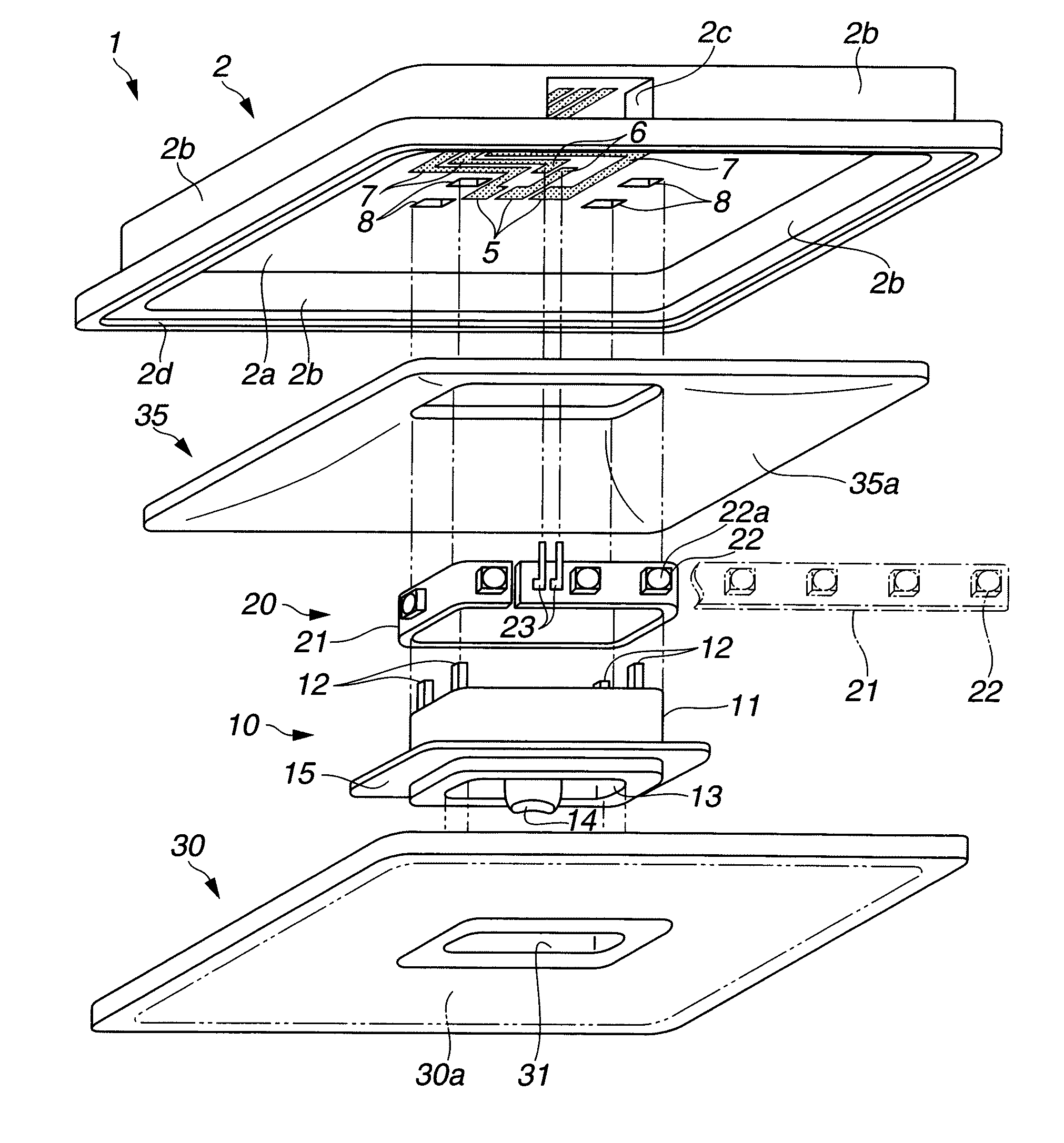
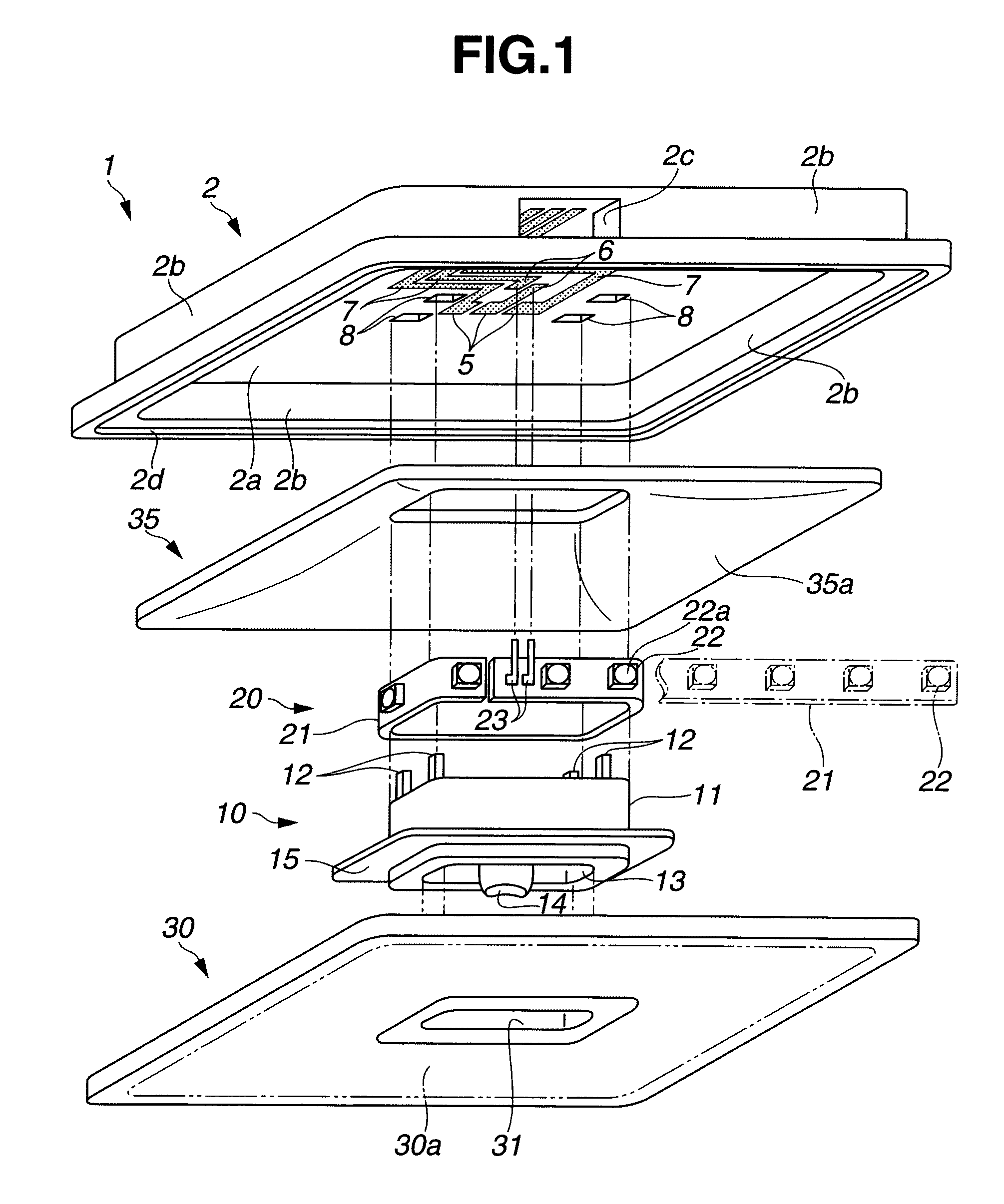
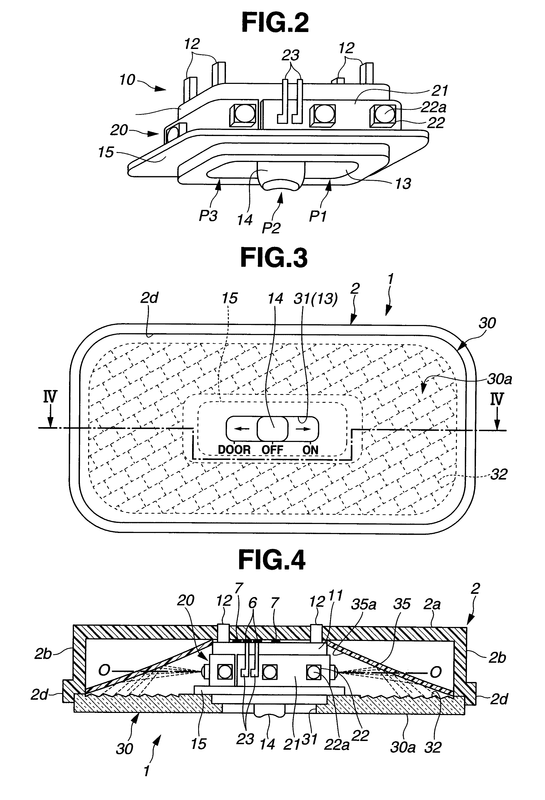
[0030]In the following, embodiments of the present invention will be described with reference to the drawings. FIGS. 1 to 8 relate to the present invention. FIG. 1 is an exploded perspective view showing parts of a room lamp, FIG. 2 is a perspective view showing a switch provided with light emitting diodes, FIG. 3 is a plan view of the room lamp, FIG. 4 is a cross-sectional view of parts of the room lamp taken along the line IV-IV in FIG. 3, FIG. 5 is a cross-sectional view of parts of a modification of the room lamp shown in FIG. 4, FIG. 6 is a diagram showing a relative light emission intensity of the light emitting diode, FIG. 7 is a plan view of a map lamp, and FIG. 8 is a cross-sectional view of parts of the map lamp taken along the line IIX-IIX in FIG. 7.

[0031]In FIGS. 1, 3 and 4, reference numeral 1 denotes a room lamp (illuminating apparatus) attached to an interior ceiling of a vehicle. The room lamp 1 has a housing 2 that has a flat box like shape and has an open bottom. T...

second embodiment

[0053]FIGS. 9 to 18C relate to the present invention. FIG. 9 is an exploded perspective view showing parts of a room lamp, FIG. 10 is a plan view of the room lamp, FIG. 11 is a cross-sectional view of parts of the room lamp taken along the line A-A in FIG. 10, FIGS. 12 to 15 are cross-sectional views of parts of modifications of the room lamp taken along the line A-A in FIG. 9, FIG. 16 is an exploded perspective view showing a relationship between a switch mechanism and a light source unit shown in FIG. 15, FIG. 17 is a cross-sectional view of parts of a modification of the room lamp taken along the line B-B in FIG. 9, FIG. 18A is an enlarged cross-sectional view showing a modification of an outer lens, and FIGS. 18B and 18C are plan views showing the inside of the outer lens in an enlarged manner.

[0054]In FIGS. 9 to 11, reference numeral 101 denotes a room lamp (illuminating apparatus) attached to an interior ceiling of a vehicle. The room lamp 101 has a housing 102 that has a flat...


PUM


Abstract

A peak of the radiation directivity of light emitted by each of LEDs is directed to a reflecting surface, and the light emitted by the LEDs is indirectly incident on an outer lens after reflection by the reflecting surface. Thus, problems, such as a local increase in brightness of a light emitting surface over areas corresponding to light emitting portions of the LEDs, are prevented. In addition, most of the light emitted by the LEDs is indirectly incident on the outer lens via the reflecting surface, so that dispersion of blue light and yellow light, which constitute the white light, by the outer lens is prevented. Thus, illumination light highly uniform in amount and color can be provided.

Description

TECHNICAL FIELD[0001]The present invention relates to an illuminating apparatus that incorporates a light emitting element, such as a light emitting diode, as a light source.BACKGROUND ART[0002]A vehicle, such as a passenger car, has a vehicle interior lamp (illuminating apparatus), such as a room lamp and a map lamp, attached to the interior ceiling. Many of the vehicle interior lamps guide light from a light source, such as a light bulb, directly or indirectly to an outer lens to provide planar light emission from the outer surface of the outer lens, thereby producing desired illumination light. For example, according to a technique disclosed in Japanese Patent Application Laid-Open Publication No. 8-16927, a lens main body (outer lens) is formed by a light guide plate. Light from a light bulb, namely a light source, is directly incident on the outer lens, so that a region of the outer lens close to the light source serves as a direct illuminating part (a close-to-light-source reg...

Claims


Application Information

Patent Timeline
Patent Type & Authority Applications(United States)
IPC IPC(8): F21V9/16F21V7/00F21V29/00F21V9/00
CPCB60Q3/0279F21Y2101/02F21W2101/08B60Q3/74F21Y2115/10F21W2106/00
Inventor YAJIMA, JUNSHIRAISHI, HIROMITSUNAGANO, MASAMITSU
Owner HARISON TOSHIBA LIGHTING CORP
Why Eureka
Try Eureka