Image forming apparatus

Active Publication Date: 2010-07-29
CANON KK
View PDF4 Cites 53 Cited by
  • Summary
  • Abstract
  • Description
  • Claims
  • Application Information

AI Technical Summary

Benefits of technology

[0009]Further, the link mechanism is required to have high rigidity. In addition, there are needs to increase a size of the

Problems solved by technology

By this mechanism, an opening and closing operativity of the cover has been deteriorated and a resultant constitution has been complicated to invite an increase in cost.
Particularly, in a color image forming apparatus in which four process cartridges are arranged, the load for disengaging and engaging

Method used


Image

  • Image forming apparatus
  • Image forming apparatus
  • Image forming apparatus

Examples


embodiment 1

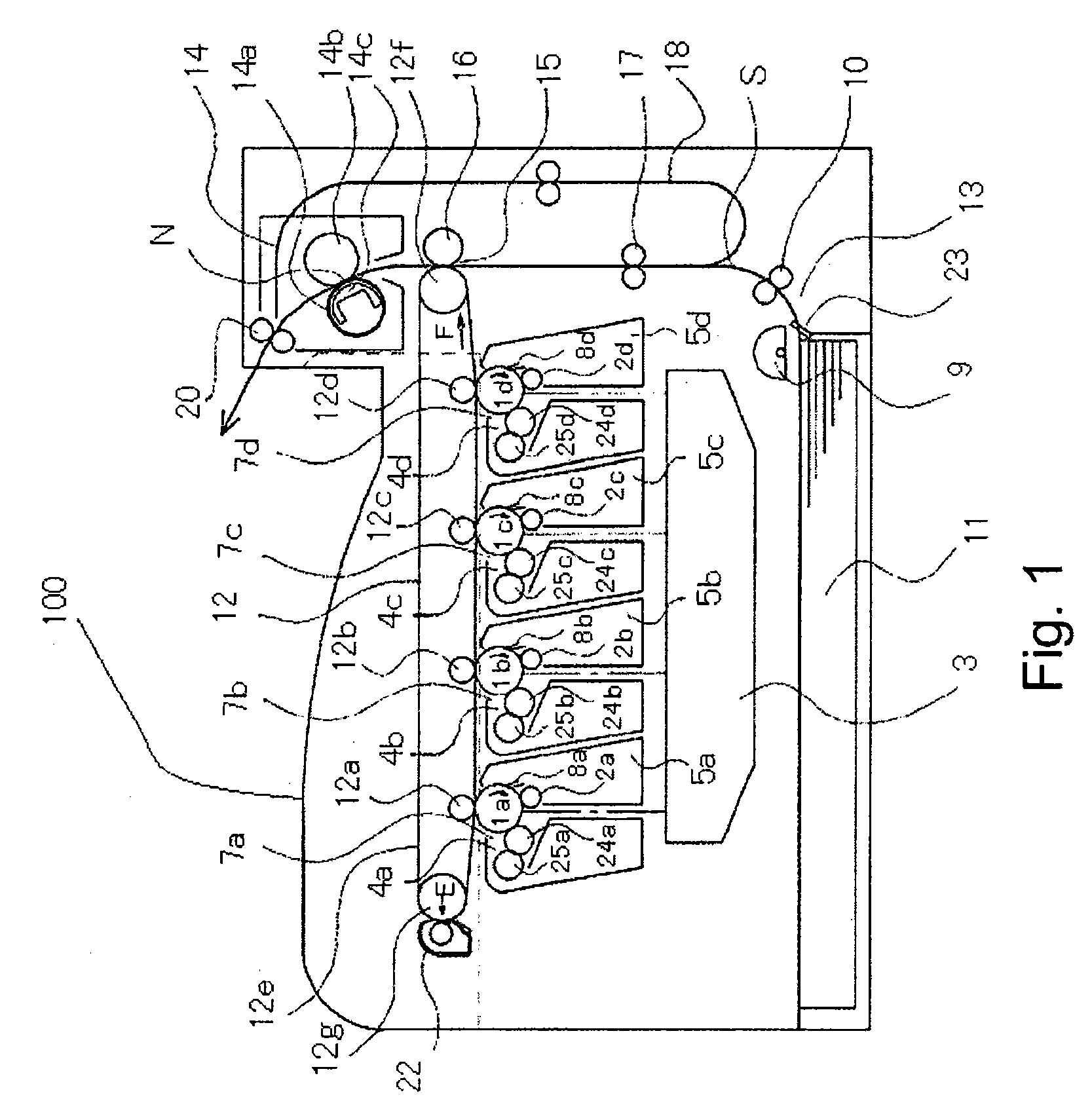
[0045]This embodiment will be described by using a four-drum type color image forming apparatus of an electrophotographic type as an apparatus main assembly and using an intermediary transfer unit as a detachably mountable unit. Further, in this embodiment, in order to transmit from the apparatus main assembly a driving force for moving a primary transfer roller in the intermediary transfer unit away from a corresponding photosensitive drum, a drive transmission device is used. The drive transmission device in this embodiment includes a first coupling and a second coupling rotating by being engaged with the first coupling.

[0046]Hereinbelow, an embodiment of the present invention will be described in the order of the image forming apparatus, the intermediary transfer unit, and the drive transmission device with reference to FIGS. 1 to 12.

[Image Forming Apparatus]

[0047]First, a constitution of an apparatus main assembly 100 will be described.

[0048]FIG. 1 is a sectional view showing an...

embodiment 2

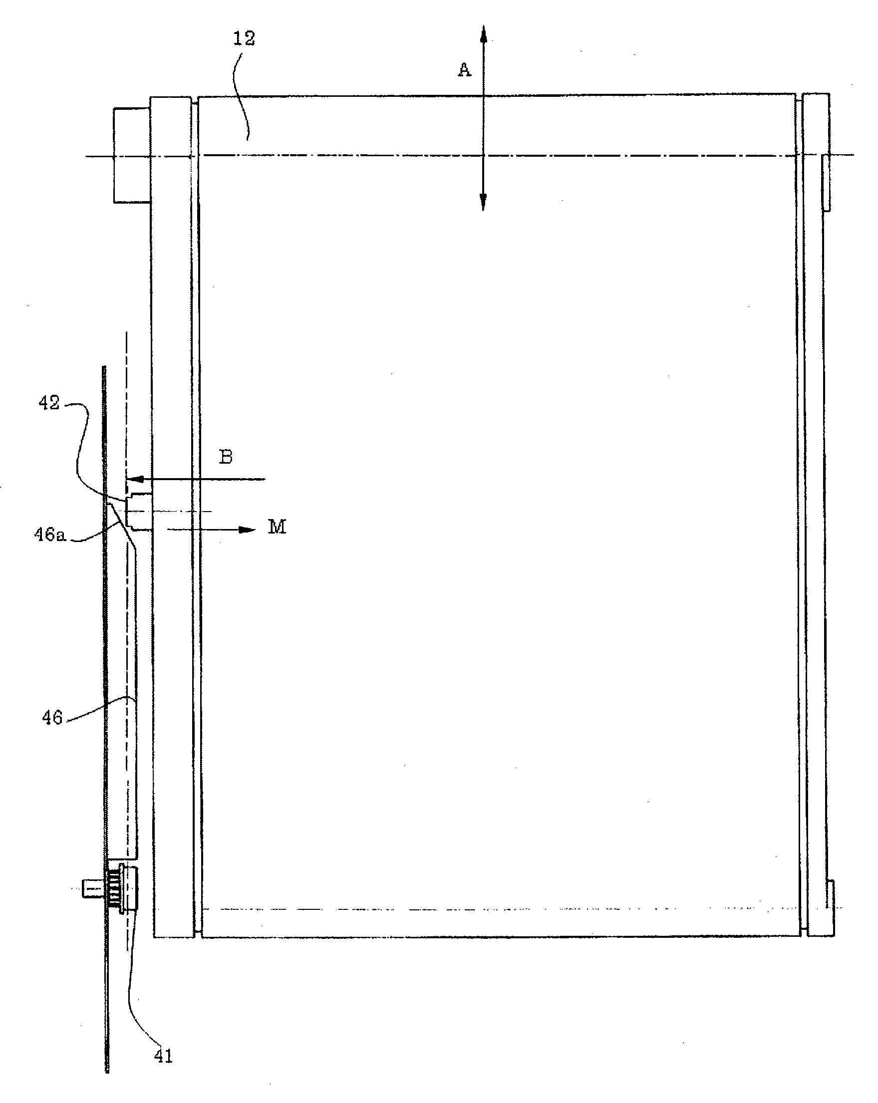
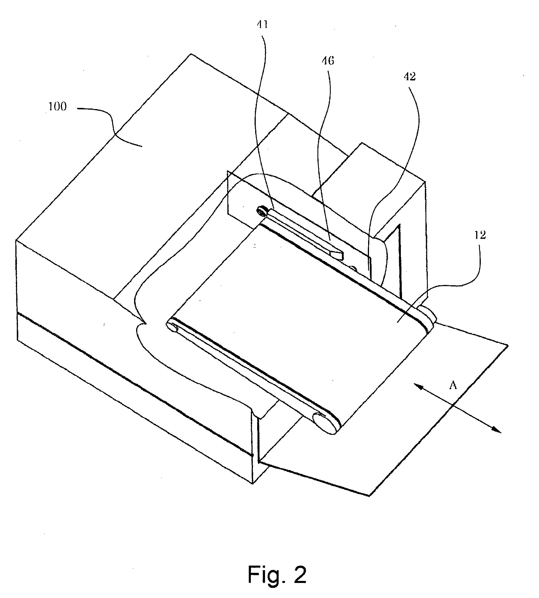
[0094]In this embodiment, a drive transmission device in which a driving cartridge 51 and a driven cartridge 52 are engaged with each other at a plurality of phases will be described. All the constitutions other than the drive transmission device are similar to those in Embodiment 1.

[0095]In the case where there is no need to control the phase on an objective unit side by the driving motor provided on the main assembly side, a similar effect can be obtained also in the constitution of the couplings shown in FIGS. 13(a) to 13(c). For example, a drive transmission device or the like for rotating unit-side rollers or the like in a predetermined direction corresponds to the constitution.

[0096]In FIGS. 13(a) to 13(c), a reference numeral 51 represents a driving cartridge corresponding to the driving cartridge 4 in Embodiment 1 and a reference numeral 52 represents a driven cartridge corresponding to the driven cartridge 42 in Embodiment 1.

[0097]The couplings in this embodiment are simila...

embodiment 3

[0101]In this embodiment, a drive transmission device in which a driving cartridge 61 and a driven cartridge 62 are engaged with each other at a plurality of phases will be described. All the constitutions other than the drive transmission device are similar to those in Embodiment 1.

[0102]Similarly as in Embodiment 2, the drive transmission device can be used in the case where there is no need to control the phase on an objective unit side by the driving motor provided on the main assembly side.

[0103]In FIGS. 18(a) to 18(c), a reference numeral 61 represents a driving cartridge corresponding to the driving cartridge 4 in Embodiment 1 and a reference numeral 62 represents a driven cartridge corresponding to the driven cartridge 42 in Embodiment 1.

[0104]The couplings in this embodiment are similar to those in Embodiment 1 except that engaging portions of the driving cartridge 61 and the driven cartridge 62 are different in shape from the couplings in Embodiment 1.

[0105]As shown in FIG...


PUM


Abstract

A unit detachably mountable to an apparatus main assembly s provided with a coupling for receiving a rotational driving force from the apparatus main assembly. Also the apparatus main assembly is provided with a coupling to be engaged with the coupling of the unit. At least one of these couplings can be pushed in a direction parallel to a rotation shaft and one of the couplings is provided with an inclined surface. During mounting and demounting of the unit, the engagement between the couplings is released by the pushing-in of one of the couplings pushed by the inclined surface.

Description

TECHNICAL FIELD[0001]The present invention relates to an image forming apparatus provided with a drive transmission device for transmitting a driving force to a unit detachably mountable to an apparatus main assembly.BACKGROUND ART[0002]In recent years, in an image forming apparatus such as a printer, a copying machine, or the like, of an electrophotographic type, downsizing and improvement in operativity have been desired.[0003]From the viewpoint of the improvement in operativity of the image forming apparatus, a process cartridge system in which a photosensitive member, a charging means, a developing means, a cleaning means, and the like are integrally assembled into a cartridge and the cartridge is detachably mountable to an image forming apparatus main assembly has been employed. By this cartridge system, the operativity was further improved, so that it became possible to easily perform maintenance of the above-described process means such as the developing means by a user himse...

Claims


Application Information

Patent Timeline
IPC IPC(8): G03G15/00
CPCG03G21/1647G03G21/186G03G2221/1642G03G2221/1657G03G15/1615F16D3/10G03G21/1857G03G15/00G03G21/16
Inventor KAWASHIMA, TOMOMICHIMIYAMOTO, TAKAYUKI
Owner CANON KK
Why Eureka
Try Eureka