Isolator

Inactive Publication Date: 2010-07-29
PHC HLDG CORP
View PDF2 Cites 21 Cited by
  • Summary
  • Abstract
  • Description
  • Claims
  • Application Information

AI Technical Summary

Benefits of technology

[0011]The present invention has been made based on such realization of the inventors, and a purpose thereof

Problems solved by technology

At this time, if there is the sterilizing material adsorbed by the particulate trap filter, the replacement process will take a long time because it is

Method used


Image

  • Isolator
  • Isolator
  • Isolator

Examples


first embodiment

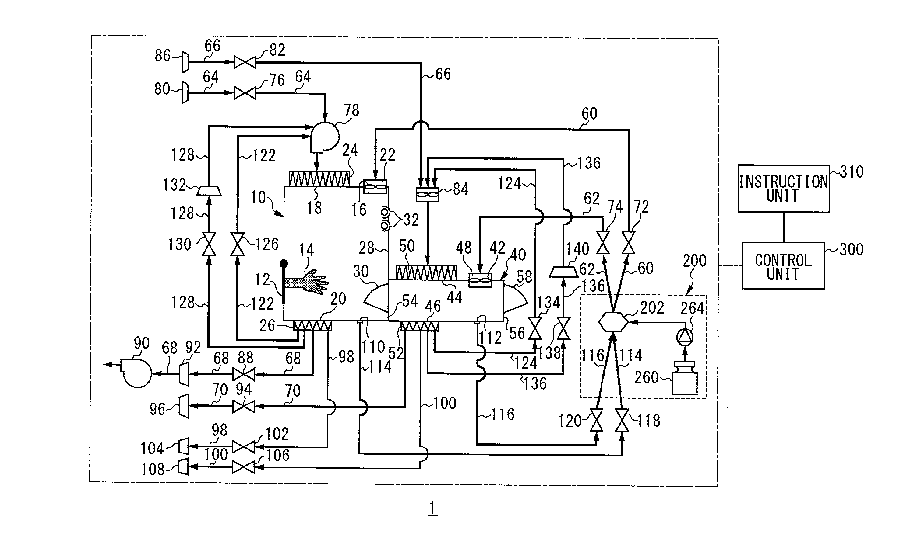
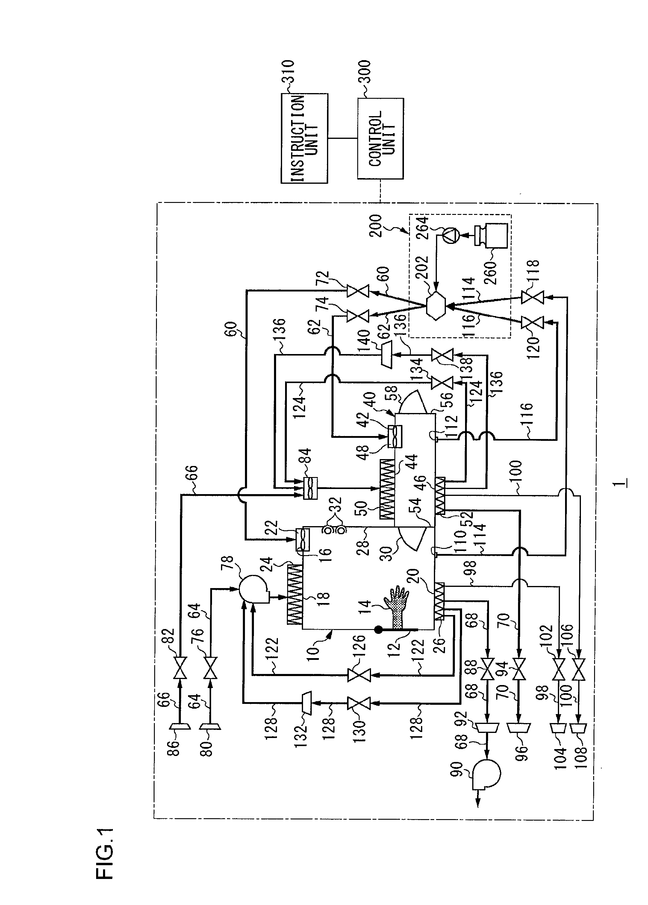
[0020]FIG. 1 is a schematic representation showing a structure of an isolator according to a first embodiment of the present invention.

[0021]As shown in FIG. 1, an isolator 1 of the first embodiment includes a workroom 10, a sterilization chamber 40, a sterilizing material supply unit 200, and a control unit 300.

[0022]The workroom 10 is a space in which work involving biologically-derived materials, such as cell extraction or cell culture, for instance, is performed. The workroom 10 is provided with a front door 12 which is openable and closable, and a work glove 14 to be used in operations in the workroom 10 is installed in a predetermined position of the front door 12. A worker can insert his / her hand into the work glove 14 through a not-shown opening provided in the front door 12 and perform work in the workroom 10 via the work glove 14. Note that biologically-derived materials meant here are materials such as living organisms themselves including cells, substances constituting t...


PUM

PropertyMeasurementUnit
Flow rateaaaaaaaaaa
Concentrationaaaaaaaaaa

Abstract

An isolator includes a workroom having a first sterilizing material supply port, a first sterilizing material discharge port, a first gas supply port and a first gas discharge port, a sterilization chamber having a second sterilizing material supply port, a second sterilizing material discharge port, a second gas supply port and a second gas discharge port, a sterilizing material supply unit, a first sterilizing material supply path connecting the sterilizing material supply unit to the first sterilizing material supply port, a second sterilizing material supply path connecting the sterilizing material supply unit to the second sterilizing material supply port, a first circulating path connecting the first sterilizing material discharge port to the sterilizing material supply unit, a second circulating path connecting the second sterilizing material discharge port to the sterilizing material supply unit, a first gas supply path, a second gas supply path, a first gas discharge path, a second gas discharge path, and a control unit.

Description

[0001]This application is based upon and claims the benefit of priority from the prior Japanese Patent Applications No. 2009-014765, filed on Jan. 26, 2009, the entire contents of which are incorporated herein by reference.BACKGROUND OF THE INVENTION[0002]1. Field of the Invention[0003]The present invention relates to a bio isolator.[0004]2. Description of the Related Art[0005]A bio isolator, an isolator for bio research, a biohazard isolator or the like is a system having a sterilized workroom, in which operations that require a sterile environment, such as those involving biologically-derived materials obtained by cell culture, for instance, are performed. The sterile environment meant here is an environment substantially free of dust and germs such that it allows no entry of substances other than the materials used in the work done in the workroom. Among conventionally known technologies for such an environment is an isolator having a sterilization chamber which is connected to a...

Claims


Application Information

Patent Timeline
IPC IPC(8): A61L2/24A61L2/00A61L2/16
CPCA61L2/208A61L2/22A61L2/24A61L2202/122A61L2202/14A61L2/022A61L9/00A61L9/015B01D45/00F24F13/28A61L2/0017C12M37/00
Inventor YOKOI, YASUHIKOOHNISHI, JIROFUKUI, SHINJIIWAMA, AKIFUMI
Owner PHC HLDG CORP
Why Eureka
Try Eureka