Well Performance Modeling In A Collaborative Well Planning Environment

Inactive Publication Date: 2010-07-29
BENISH TIMOTHY G +4
View PDF38 Cites 203 Cited by
  • Summary
  • Abstract
  • Description
  • Claims
  • Application Information

AI Technical Summary

Benefits of technology

[0010]Embodiments of the present invention generally provide methods and apparatus for modeling well performance in a collaborative three-dimensional well planning environment.
[0011]One embodiment provides a method for well planning incorporating well completion design in a collaborative environment. The method generally includes specifying one or more wellpath parameters defining a wellpath to a target (or set of targets) within an earth model stored in memory, specifying one or more operating parameters defining a completion operation, simulating the completion operations using the earth model based on the wellpath parameters and the completion parameters to generate a set of well performance measures, and determining whether the well performance measures are within defined well performance technical limits. If the well performance measures are within the defined well performance technical limits, optimizing well placement within the earth model stored in memory in order to maximize an objective function and if the well performance parameters are not within the defined well performance technical limits, adjusting one or more of the wellpath parameters, the completion parameters, and any combination thereof to generate adjusted parameters and repeating the simulating operations utilizing the adjusted parameters.
[0012]One embodiment provides a computer-readable medium containing a program which, when executed, performs instructions associated with well planning incorporating well completion design in a collaborative environment. The instructions are configured to provide a graphical user interface (GUI), which may allow one or more users to specify one or more wellpath parameters defining a wellpath to at least one target within an earth model of at least one reservoir and to specify one or more completion parameters defining completion operations, simulate the com

Problems solved by technology

Because of the cost and economic risk associated with drilling a new well, proper well placement significantly impacts the cost of producing the hydrocarbons as well as the maximum production rates and ultimate recovery of the hydrocarbons.
This process may be repeated for each location of possible interest, often at great expense.
That is, these s

Method used


Image

  • Well Performance Modeling In A Collaborative Well Planning Environment
  • Well Performance Modeling In A Collaborative Well Planning Environment
  • Well Performance Modeling In A Collaborative Well Planning Environment

Examples


Embodiment Construction

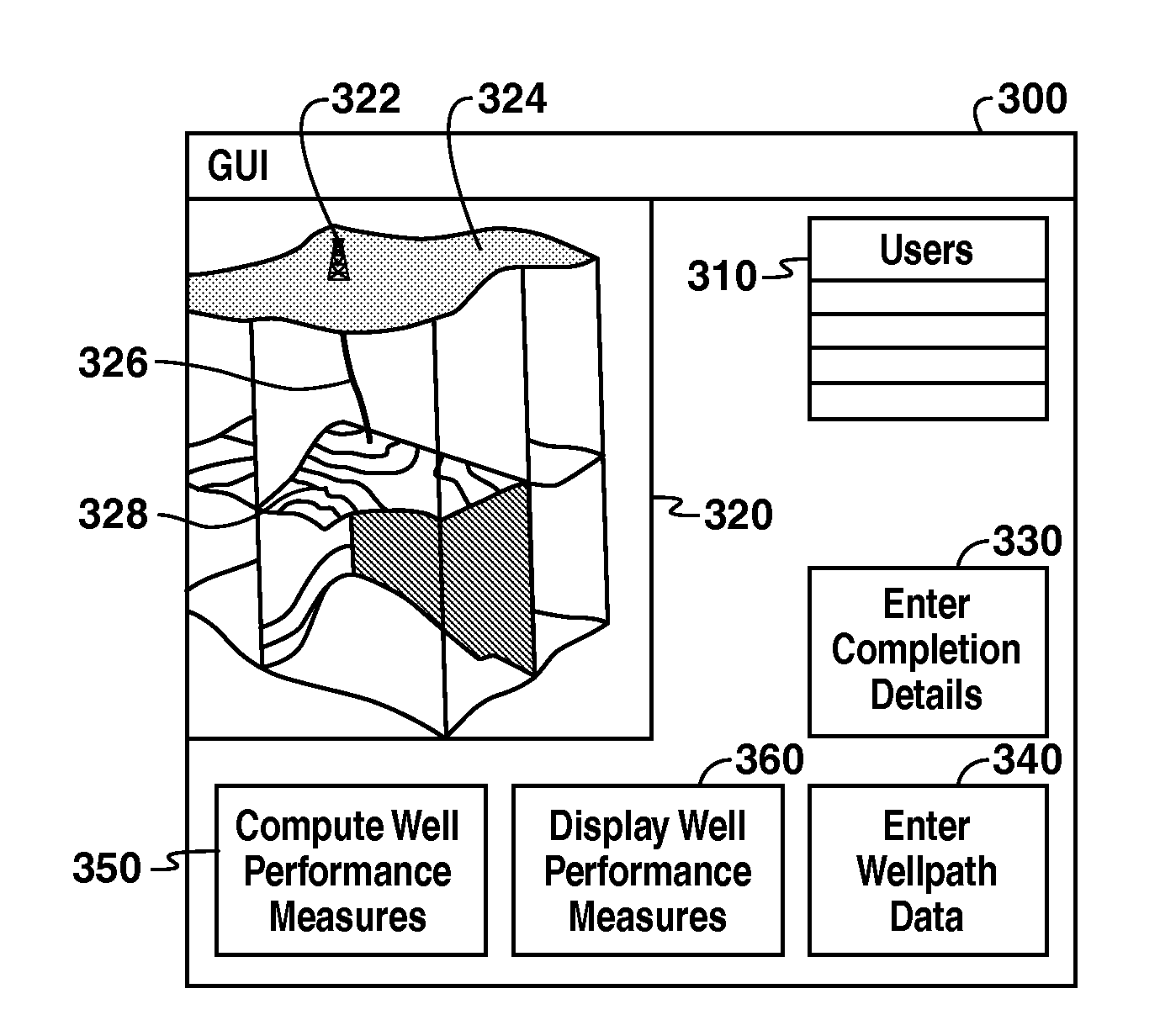
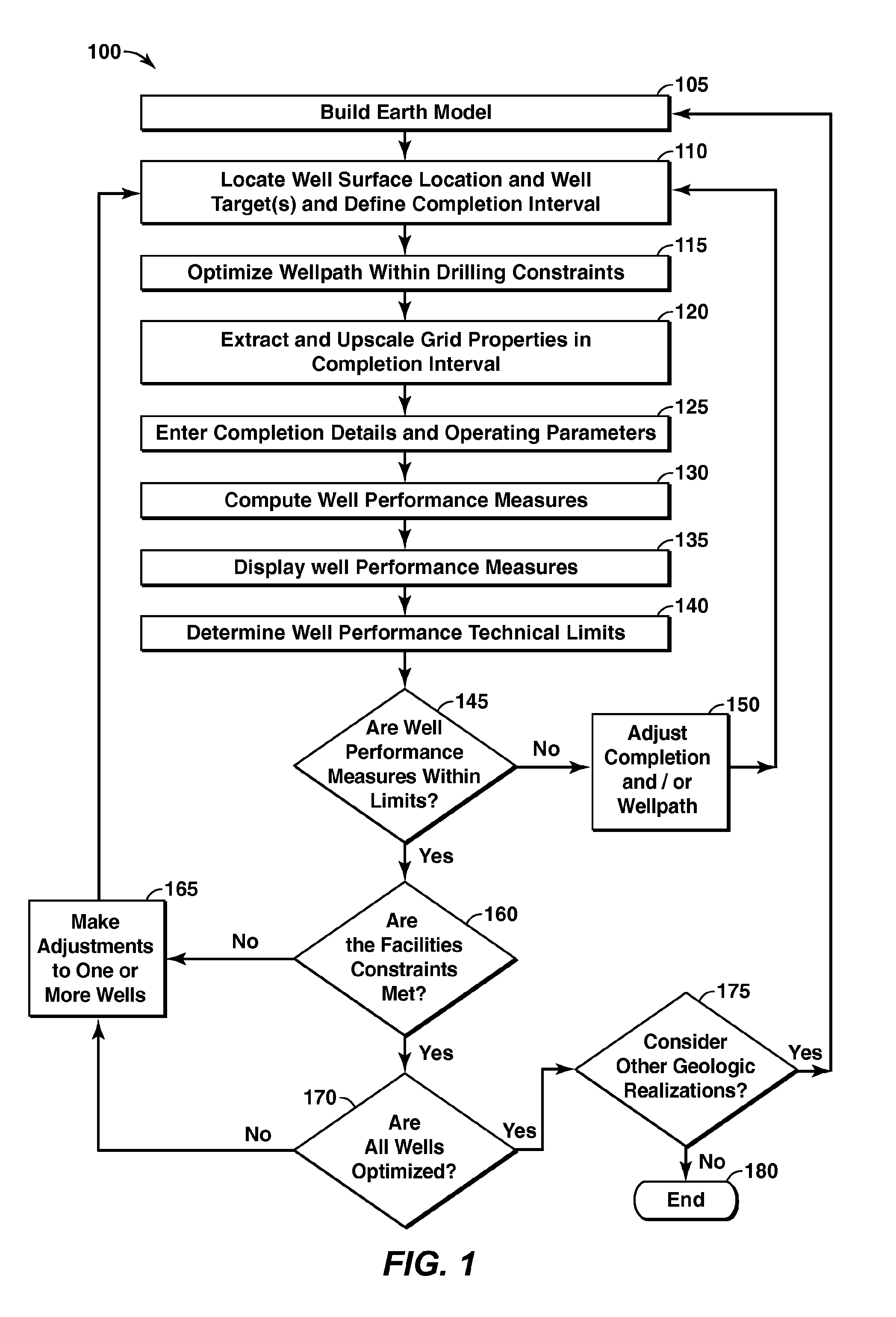
[0023]Embodiments of the present invention may be utilized to make completion design an integral part of the well planning process by enabling the rapid evaluation of completion performance. This integration may include considering producibility (e.g. flow capacity) and operability (e.g. mechanical integrity) in well placement exercises within a collaborative environment.

[0024]The evaluation of well placement and completion design may utilize an earth model to enhance the well planning process. An earth model is a one, two, three or four dimensional representation of the subsurface area of interest, which typically is from the earth's surface to below the depth of the deepest well to be planned. The earth model is intended to represent the most comprehensive understanding of the subsurface, and may include both geologic and engineering data. Typically, it includes data relating to well bores, well logs, interpreted horizons and faults derived from wells and seismic, estimates of roc...


PUM


Abstract

Methods and systems are provided that may be utilized to make completion design an integral part of the well planning process by enabling the rapid evaluation of completion performance. This integration may include an earth model and may specify wellpath parameters, completion parameters, and other parameters in a simulation of operations using the earth model. The simulation generates well performance measures, which may be optimized depending on well performance technical limits. The optimization may be used to maximize an objective function. The system may include multiple users at the same or different locations (e.g. over a network) interacting through graphic user interfaces (GUI's).

Description

CROSS REFERENCE TO RELATED APPLICATIONS[0001]This application is the National Stage entry under 35 U.S.C. 371 of PCT / US2008 / 070778, that published as WO 2009 / 032416 and was filed 22 Jul. 2008, which claims the benefit of U.S. Provisional Application No. 60 / 967,804, filed 7 Sep. 2007, each of which is incorporated herein by reference, in its entirety, for all purposes.BACKGROUND[0002]The present invention generally relates to methods for maximizing the efficiency of locating and extracting petroleum from a subsurface location. More specifically, the present invention relates to providing a collaborative three-dimensional well planning environment.DESCRIPTION OF THE RELATED ART[0003]A reservoir may include one or more subsurface rock formations. These subsurface rock formations are porous and permeable and may contain liquid and gaseous hydrocarbons. The degree of porosity relates to the volume of fluid contained within the reservoir. The permeability relates to the ability of the flu...

Claims


Application Information

Patent Timeline
IPC IPC(8): G06G7/48
CPCE21B43/00
Inventor BENISH, TIMOTHY G.CLINGMAN, SCOTT R.DALE, BRUCE A.HOLL, JAMES E.MUSUM, RUNE
Owner BENISH TIMOTHY G
Why Eureka
Try Eureka